Intel D915GMH Product Specification
Intel D915GMH Manual
 |
View all Intel D915GMH manuals
Add to My Manuals
Save this manual to your list of manuals |
Intel D915GMH manual content summary:
- Intel D915GMH | Product Specification - Page 1
December 2004 Order Number: C81296-001 The Intel® Desktop Board D915GMH may contain design defects or errors known as errata that may cause the product to deviate from published specifications. Current characterized errata are documented in the Intel Desktop Board D915GMH Specification Update. - Intel D915GMH | Product Specification - Page 2
Date December 2004 This product specification applies to only standard Intel® Desktop Board D915GMH with BIOS identifier EV91510A.86A. Changes to this specification will be published in the Intel Desktop Board D915GMH Specification Update before being incorporated into a revision of this document - Intel D915GMH | Product Specification - Page 3
Contains Chapter 1 2 3 4 Description A description of the hardware used on the Desktop Board D915GMH A map of the resources of the Desktop Board The features supported by the BIOS Setup program A description of the BIOS error messages, beep codes, and POST codes Typographical Conventions This - Intel D915GMH | Product Specification - Page 4
Intel Desktop Board D915GMH Technical Product Specification Other Common Notation # (NxnX) GB GB/ the relative coordinates of its location on the Desktop Board D915GMH, and X is the instance of the particular part at that general location. For example, J5J1 is a connector, located at 5J. It is the - Intel D915GMH | Product Specification - Page 5
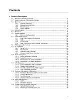
Feature Summary 12 1.3.2 Manufacturing Options 13 1.3.3 Board Layout 14 1.3.4 Block Diagram 16 1.4 Online Support ...17 1.5 Processor ...17 1.6 System Memory ...18 1.6.1 Memory Configurations 20 1.7 Intel® 915G Chipset ...24 1.7.1 Intel 915G Graphics Subsystem 24 1.7.2 USB ...26 1.7.3 IDE - Intel D915GMH | Product Specification - Page 6
Intel Desktop Board D915GMH Technical Product Specification 1.14.3 1.14.4 1. Board Level 84 3 Overview of BIOS Features 3.1 Introduction ...85 3.2 BIOS Flash Memory Organization 86 3.3 Resource Configuration 86 3.3.1 PCI Autoconfiguration 86 3.3.2 PCI IDE Support 86 3.4 System Management BIOS - Intel D915GMH | Product Specification - Page 7
3.6 BIOS Updates ...88 3.6.1 Language Support 88 3.6.2 Custom Splash Screen 88 3.7 Boot Options ...89 3.7.1 CD-ROM Boot 89 3.7.2 Network Boot 89 3.7.3 Booting Without Attached Devices 89 3.7.4 Changing the Default Boot Device During POST 89 3.8 Fast Booting Systems with Intel® Rapid BIOS Boot - Intel D915GMH | Product Specification - Page 8
Intel Desktop Board D915GMH Technical Product Specification 27. I/O Shield Dimensions for Boards with the 6-channel (5.1) Audio Subsystem 75 28. Localized High Temperature Zones 78 Tables 1. Feature Summary ...12 2. Manufacturing Options 13 3. Board Components Shown in Figure 1 15 4. Supported - Intel D915GMH | Product Specification - Page 9
Contents 44. Boot Device Menu Options 89 45. Supervisor and User Password Functions 91 46. BIOS Error Messages 93 47. Uncompressed INIT Code Checkpoints 95 48. Boot Block Recovery Code Checkpoints 95 49. Runtime Code Uncompressed in F000 Shadow RAM 96 - Intel D915GMH | Product Specification - Page 10
Intel Desktop Board D915GMH Technical Product Specification x - Intel D915GMH | Product Specification - Page 11
Connector Terminology Change 11 1.3 Overview ...12 1.4 Online Support ...17 1.5 Processor ...17 1.6 System Memory ...18 1.7 Intel® 915G Chipset ...24 1.8 PCI Express Connectors 28 1.9 I/O Controller...29 1.10 Audio Subsystem ...30 1.11 LAN Subsystem ...35 1.12 Hardware Management Subsystem 38 - Intel D915GMH | Product Specification - Page 12
1 summarizes the major features of the Desktop Board D915GMH. Table 1. Feature Summary Form Factor Processor Memory microBTX Form Factor (10.50 inches by 10.40 inches [266.70 millimeters by 264.16 millimeters]) Support for an Intel® Pentium® 4 processor in an LGA775 socket with an 800 or 533 MHz - Intel D915GMH | Product Specification - Page 13
speed control 1.3.2 Manufacturing Options Table 2 describes the manufacturing options on the Desktop Board D915GMH. Not every manufacturing option is available in all marketing channels. Please contact your Intel representative to determine which manufacturing options are available to you. Table - Intel D915GMH | Product Specification - Page 14
Intel Desktop Board D915GMH Technical Product Specification 1.3.3 Board Layout Figure 1 shows the location of the major components on the Desktop Board D915GMH. Line In RJ45 A X W V U T S BC D Intel R 82801 (ICH) Intel R 82915G R (GMCH) Q P O NM Figure 1. Board Components E F G H I J K L - Intel D915GMH | Product Specification - Page 15
power connector (1 x 4) Diskette drive connector BIOS Setup Configuration Jumper IEEE 1394a connectors (optional) Front chassis fan connector Front panel connector Alternate power LED connector Processor socket Processor core power connector (2 x 2) Processor fan header (4-pin, fan speed control - Intel D915GMH | Product Specification - Page 16
DMI Interconnect High Definition Audio Link LAN Connect Interfac e LPC Bus Parallel ATA IDE Connector Parallel ATA IDE Interface LGA775 Processor Socket System Bus (800/533 MHz) PCI Express x16 Interface PCI Express x16 Connector Intel 82915G Graphics and Memory Controller Hub (GMCH) VGA - Intel D915GMH | Product Specification - Page 17
for the Desktop Board D915GMH Processor data sheets ICH6 addressing Custom splash screens Audio software and utilities LAN software and drivers Visit this World Wide Web site: http://www.intel.com/design/motherbd http://support.intel.com/support/motherboards/desktop http://developer.intel.com - Intel D915GMH | Product Specification - Page 18
Intel Desktop Board D915GMH Technical Product Specification 1.6 System Memory The board has four DIMM sockets and support the following memory features: • 2.5 V (only) DDR SDRAM DIMMs with gold-plated contacts • Unbuffered, single-sided or double-sided DIMMs with the following restriction: Double- - Intel D915GMH | Product Specification - Page 19
Product Description Table 5 lists the supported DIMM configurations. Table 5. Supported Memory Configurations DIMM Capacity SDRAM Configuration Density SDRAM Organization Front-side/Back-side Number of SDRAM Devices 128 MB SS 256 Mbit 16 M x 16/empty 4 256 - Intel D915GMH | Product Specification - Page 20
Intel Desktop Board D915GMH Technical Product Specification 1.6.1 Memory Configurations The Intel 82915G GMCH supports two types of memory organization: • Dual channel (Interleaved) mode. This mode offers the highest throughput for real world applications. Dual channel mode is enabled when the - Intel D915GMH | Product Specification - Page 21
DIMMs. In this example, the combined capacity of the two DIMMs in Channel A equal the capacity of the single DIMM in the DIMM0 (blue) socket of Channel B. 256 MB 256 MB 512 MB Channel A, DIMM 0 Channel A, DIMM 1 Channel B, DIMM 0 Channel B, DIMM 1 OM17122 Figure 5. Dual Channel (Interleaved) Mode - Intel D915GMH | Product Specification - Page 22
Intel Desktop Board D915GMH Technical Product Specification Figure 6 shows a dual channel configuration using four DIMMs. In this example, the combined capacity of the two DIMMs in Channel A equal the - Intel D915GMH | Product Specification - Page 23
highest memory throughput. Figure 7 shows a single channel configuration using one DIMM. In this example, only the DIMM0 (blue) socket of in Channel A does not equal the capacity of the single DIMM in the DIMM0 (blue) socket of Channel B. 256 MB 512 MB 512 MB Channel A, DIMM 0 Channel A, DIMM 1 - Intel D915GMH | Product Specification - Page 24
Intel Desktop Board D915GMH Technical Product Specification 1.7 Intel® 915G Chipset The Intel 915G chipset consists of the following devices: • Intel 82915G Graphics Memory Controller Hub (GMCH) with Direct Media Interface (DMI) interconnect • Intel 2 (ADD2-R) card support flat panel displays up - Intel D915GMH | Product Specification - Page 25
• Dynamic Video Memory Technology (DVMT) support up to 224 MB • Intel® Zoom Utility BIOS Setup program) for compatibility with legacy applications. An example of this would be when using VGA graphics under DOS. Once loaded, the operating system and graphics drivers allocate additional system memory - Intel D915GMH | Product Specification - Page 26
Intel Desktop Board D915GMH Technical Product Specification NOTE This board supports ADD2-R cards only. Other types of ADD2 cards are not compatible with this board. 1.7.2 USB The board supports up to eight USB 2.0 ports, supports UHCI and EHCI, and uses UHCI- and EHCI-compatible drivers. The ICH6 - Intel D915GMH | Product Specification - Page 27
The drive reports the transfer rate and translation mode to the BIOS. The board supports Laser Servo (LS-120) diskette technology through the Parallel ATA about The location of the Serial ATA IDE connectors Refer to Figure 20, page 64 1.7.3.3 Serial ATA RAID The optional ICH6-R supports RAID ( - Intel D915GMH | Product Specification - Page 28
Intel Desktop Board D915GMH Technical Product Specification 1.7.3.4 RAID Boot Configuration Overview A RAID array can be created by using the existing Serial ATA ports, correctly configuring the BIOS, and installing drivers. The following steps are required to successfully establish a RAID - Intel D915GMH | Product Specification - Page 29
configuration options for the I/O controller. 1.9.1 Serial Port Serial port A is located on the back panel. The serial port supports data transfers at speeds up to 115.2 kbits/sec with BIOS support. For information about The location of the serial port A connector Refer to Figure 19, page 62 - Intel D915GMH | Product Specification - Page 30
Intel Desktop Board D915GMH Technical Product Specification 1.9.4 Keyboard and Mouse Interface PS/2 keyboard and mouse connectors are located on the back panel. ✏ NOTE The keyboard is supported in the bottom PS/2 connector and the mouse is supported in the top PS/2 connector. Power to the computer - Intel D915GMH | Product Specification - Page 31
Product Description 1.10.1 Audio Subsystem Software Audio software and drivers are available from Intel's World Wide Web site. For information about Refer to Obtaining audio software and drivers Section 1.4, page 17 1.10.2 Audio Connectors The board contains audio connectors on both the back - Intel D915GMH | Product Specification - Page 32
Intel Desktop Board D915GMH Technical Product Specification 1.10.3 8-Channel (7.1) Audio Subsystem The 8-channel (7.1) audio subsystem includes the following: • Intel 82801FR I/O Controller Hub (ICH6) • Realtek ALC880 audio codec • Microphone input that supports a single dynamic, condenser, or - Intel D915GMH | Product Specification - Page 33
Product Description Figure 10 is a block diagram of the 8-channel (7.1) audio subsystem. 82801FB I/O Controller Hub (ICH6) Intel High Definition Audio Link Realtek ALC880 Audio Codec Mic In/Retasking Jack B Line In/Retasking Jack C Line Out/Retasking Jack D Front Panel Retasking Jack A/E [Port - Intel D915GMH | Product Specification - Page 34
Intel Desktop Board D915GMH Technical Product Specification 1.10.4 6-Channel (5.1) Audio Subsystem The 6-channel (5.1) audio subsystem includes the following: • Intel 82801FB I/O Controller Hub (ICH6) • Realtek ALC860 audio codec • Microphone input that supports a single dynamic, condenser, or - Intel D915GMH | Product Specification - Page 35
• CSMA/CD protocol engine • LAN connect interface that supports the 82562EZ • PCI Conventional bus power management ⎯ Supports ACPI technology ⎯ Supports LAN wake capabilities 1.11.1 10/100 Mbits/sec LAN Subsystem The 10/100 Mbits/sec LAN subsystem includes the ICH6, the Intel 82562EZ PLC, and an RJ - Intel D915GMH | Product Specification - Page 36
Intel Desktop Board D915GMH Technical Product Specification Table 6 describes the LED states when the board is powered up and the 10/100 Mbits/sec LAN subsystem is operating. Table 6. LAN Connector LED States LED Color Green Yellow LED State Off On Blinking Off On Condition LAN link is not - Intel D915GMH | Product Specification - Page 37
ASF support for the onboard 10/100/1000 LAN subsystem, PCI Express x1 bus add-in LAN cards, and PCI Conventional bus add-in LAN cards installed in PCI Conventional bus slot 2: • Monitoring of system firmware progress events, including: ⎯ BIOS present ⎯ Primary processor initialization ⎯ Memory - Intel D915GMH | Product Specification - Page 38
Intel Desktop Board D915GMH Technical Product Specification 1.11.4 LAN Subsystem Software LAN software and drivers are available from Intel's World Wide Web site. For information about Refer to Obtaining LAN software and drivers direct monitoring of processor temperature and ambient temperature - Intel D915GMH | Product Specification - Page 39
1.12.2 Thermal Monitoring Figure 15 shows the location of the sensors and fan connectors. Product Description E B Intel R 82801 (ICH) Intel R 82915G (GMCH) C D A F Item A B C D E F Description Thermal diode, located on processor die Remote ambient temperature sensor Ambient temperature - Intel D915GMH | Product Specification - Page 40
Intel Desktop Board D915GMH Technical Product Specification 1.12.3 Fan Monitoring Fan monitoring can be implemented using Intel® Desktop Utilities, LANDesk* software, or thirdparty software. The level of monitoring and control is dependent on the hardware monitoring ASIC used with the Desktop Board - Intel D915GMH | Product Specification - Page 41
the power states supported by the board along with the from the computer. Sleeping States S0 - working S1 - Processor stopped S3 - Suspend to RAM. Context saved Service can be performed safely. Notes: 1. Total system power is dependent on the system configuration, including add-in boards - Intel D915GMH | Product Specification - Page 42
Intel Desktop Board D915GMH Technical Product Specification 1.13.1.2 Wake-up Devices and Events Table 10 lists the devices or specific events that can wake the computer from specific states. Table 10. Wake-up Devices and Events These devices/events can wake up the computer... LAN Modem (back - Intel D915GMH | Product Specification - Page 43
full ACPI support. 1.13.2.1 Power Connector BTX-compliant power feature in the BIOS Setup program's Boot menu. For information about The location of the main location of the fan connectors The location of the fan connectors and sensors for thermal monitoring The signal names of the processor - Intel D915GMH | Product Specification - Page 44
Intel Desktop Board D915GMH Technical Product Specification 1.13.2.3 LAN Wake Capabilities CAUTION For LAN wake capabilities, the +5 V standby line for the power supply must be capable of providing adequate +5 V standby current. Failure to provide adequate standby current when implementing LAN wake - Intel D915GMH | Product Specification - Page 45
, S3, S4, or S5 state (with Wake on PME enabled in BIOS). 1.13.2.9 WAKE# Signal Wake-up Support When the WAKE# signal on the PCI Express bus is asserted, the connected to the board. Failure to do so could damage the board and any attached devices. OM17190 Figure 16. Location of the Standby Power Indicator - Intel D915GMH | Product Specification - Page 46
• Intel Desktop Board D915GMH • Microsoft Windows 2000 Professional (SP4) or Microsoft Windows XP Professional (SP1) • NTFS file system required • Microsoft Internet Explorer* 5.5 or later • Adobe* Acrobat* 5.0 or later 1.14.2 Warning of Potential Data Loss CAUTION Failure to follow the instructions - Intel D915GMH | Product Specification - Page 47
good password should consist of: • At least one upper case letter (A to Z) • At least one numerical character &, etc.) Example Passwords: "I wear a Brown hat 2 worK @ least once-a-month" or "uJGFak&%)adf35a9m" NOTE Avoid using , store them in a secured location (vault, safe deposit box, off-site - Intel D915GMH | Product Specification - Page 48
Intel Desktop Board D915GMH Technical Product Specification 1.14.3.2 Emergency Recovery File Back Up Procedures The (clear text) files may then be backed up to a removable media and stored in a secure location. The advantage of the clear text backup is that no TPM key is required to restore the data - Intel D915GMH | Product Specification - Page 49
POST screen), press the key to enter BIOS. 2. Use the arrow keys to go to the Advanced System should reboot and start Microsoft Windows. 1.14.6 Assuming Trusted Platform Module , the removable media should be stored in a secure location. No copies of this Emergency Recovery Token file should - Intel D915GMH | Product Specification - Page 50
Intel Desktop Board D915GMH Technical Product Specification 15. Follow the instructions and create and document the locations for both the archive and restoration key files. The key archive should be located on a removable media and stored in a secure location when not in use. 16. Create and - Intel D915GMH | Product Specification - Page 51
passwords, files, and file locations as requested by the Key Transfer Manager. 11. Upon successful completion of all steps, you should be able to access previously encrypted files. 1.14.8 Clearing Trusted Platform Module Ownership WARNING Disconnect the desktop board's power supply from its AC - Intel D915GMH | Product Specification - Page 52
Intel Desktop Board D915GMH Technical Product Specification 1.14.9 Software Support • For assistance with the Infineon Security Platform Software, visit the web at: http://www.infineon.com • For assistance with the Wave System EMBASSY Trust Suite, visit the web at: http://www.wave.com/support/ets. - Intel D915GMH | Product Specification - Page 53
2.2.1 Addressable Memory The board utilizes 4 GB of addressable system memory. Typically the address space that is allocated for PCI Conventional bus add-in cards, PCI Express configuration space, BIOS (firmware hub), and chipset overhead resides above the top of DRAM (total system memory). On - Intel D915GMH | Product Specification - Page 54
Intel Desktop Board D915GMH Technical Product Specification The amount of installed memory that can be used will vary based on add-in cards and BIOS settings. Figure 17 shows a schematic of the system memory map. All installed system memory can be used when there is no overlap of system addresses. - Intel D915GMH | Product Specification - Page 55
(open to the PCI Conventional bus). Dependent on video adapter used. Video memory and BIOS Extended BIOS data (movable by memory manager software) Extended conventional memory Conventional memory 2.3 DMA Channels Table 12. DMA Channels DMA Channel Number 0 1 2 3 4 5 6 7 Data Width 8 or 16 bits - Intel D915GMH | Product Specification - Page 56
Intel Desktop Board D915GMH Technical Product Specification 2.4 Fixed I/O Map Table 13. I/O Map Address (hex) Size Description 0000 - 00FF 0170 - 0177 256 bytes 8 bytes Used by the Desktop Board D915GMH. Refer to the ICH6 data sheet for dynamic addressing information. Secondary Parallel ATA - Intel D915GMH | Product Specification - Page 57
01 02 03 07 00 00 01 02 03 00 00 Description Memory controller of Intel 82915G component PCI Express x16 graphics port (Note 1) Integrated graphics controller Integrated graphics controller Intel High Definition Audio Controller PCI Express port 1 (PCI Express x1 bus connector 1) PCI Express port - Intel D915GMH | Product Specification - Page 58
Intel Desktop Board D915GMH Technical Product Specification 2.6 Interrupts The interrupts can be routed through either the Programmable Interrupt Controller (PIC) or the Advanced Programmable Interrupt Controller (APIC) portion of the ICH6 component. The PIC is supported in Windows 98 SE and - Intel D915GMH | Product Specification - Page 59
between devices attached to the PCI Conventional bus. In most cases, the small amount of latency added by interrupt sharing does PIRQ signals. Some PCI Conventional interrupt sources are electrically tied together on the board and therefore share the same interrupt. Table 16 shows an example of how - Intel D915GMH | Product Specification - Page 60
Intel Desktop Board D915GMH Technical Product Specification 2.8 Connectors CAUTION Only the following connectors upon which audio subsystem is present. The configurations are as follows: • 8-channel (7.1) audio subsystem (five analog audio output connectors and two digital audio output connectors), - Intel D915GMH | Product Specification - Page 61
(7.1) Audio Subsystem Figure 18 shows the location of the back panel connectors for boards equipped with the 8-channel (7.1) audio subsystem. IEEE-1394a connector (optional) LAN Audio line in/Retasking Jack C [Blue] Front left/right channel audio out/Two channel audio line out/Retasking Jack D - Intel D915GMH | Product Specification - Page 62
Intel Desktop Board D915GMH Technical Product Specification 2.8.1.2 Back Panel Connectors For 6-Channel (5.1) Audio Subsystem Figure 19 shows the location of the back panel connectors for boards equipped with the 6-channel (5.1) audio subsystem. A B C D E K J I H GF OM17328 Figure 19. - Intel D915GMH | Product Specification - Page 63
19 A B C D E F G H I J K Description PS/2 mouse port [Green] Parallel port [Burgundy] IEEE-1394a connector (optional) LAN Audio line in/Retasking Jack C [Blue] Front left/right channel audio out/Two channel audio line out/Retasking Jack D [Lime green] Mic in/Retasking Jack B [Pink] USB ports (four - Intel D915GMH | Product Specification - Page 64
Intel Desktop Board D915GMH Technical Product Specification 2.8.2 Component-side Connectors Figure 20 shows the locations of the component-side connectors. A BC D U T S R Q Intel R 82801 (ICH) Intel R 82915G (GMCH) P O NM Figure 20. Component-side Connectors Table 19 lists the component - Intel D915GMH | Product Specification - Page 65
I J K L M N O P Q R S T U Description Front panel audio connector Chassis intrusion connector Main Power connector Front panel USB connectors PCI Express x1 bus add-in Auxiliary front panel power LED connector Processor core power connector (2 x 2) Processor fan connector Parallel ATA IDE connector - Intel D915GMH | Product Specification - Page 66
Intel Desktop Board D915GMH Technical Product Specification Table 22. Front Panel Audio Connector Pin Signal Name 1 Port E [Port 1] Left Channel 3 Port E [Port 1] Signal Name 1 Control 2 +12 V 3 Tach Table 24. Processor Fan Connector Pin Signal Name 1 Ground 2 +12 V 3 FAN_TACH - Intel D915GMH | Product Specification - Page 67
Intel Desktop boards. The board supports the use of power supplies with either 2 x 10 or 2 x 12 main power cables. When using a power supply with a 2 x 10 main power cable, attach that cable on the rightmost pins of the main power connector, leaving pins 11, 12, 23, and 24 unconnected. • Processor - Intel D915GMH | Product Specification - Page 68
Intel Desktop Board D915GMH Technical Product Specification Table 28. Processor Core Power Connector Pin Signal Name Pin 1 Ground 2 3 +12 V 4 add-in cards with SMBus support can access sensor data and other information residing on the Desktop Board. Note the following considerations for - Intel D915GMH | Product Specification - Page 69
Technical Reference 2.8.2.3 Auxiliary Front Panel Power/Sleep LED Connector Pins 1 and 3 of this connector duplicate the signals on pins 2 and 4 of the front panel connector. Table 30. Auxiliary Front Panel Power/Sleep LED Connector Pin Signal Name 1 HDR_BLNK_GRN 2 Not connected 3 - Intel D915GMH | Product Specification - Page 70
Intel Desktop Board D915GMH Technical Product Specification 2.8.2.4.1 Hard Drive Activity LED single pole, single throw (SPST) type switch that is normally open. When the switch is closed, the board resets and runs the POST. 2.8.2.4.3 Power/Sleep LED Connector [Green] Pins 2 and 4 [Green] can - Intel D915GMH | Product Specification - Page 71
Technical Reference 2.8.2.5 Front Panel USB Connectors Figure 22 is a connection diagram for the front panel USB connectors. # INTEGRATOR'S NOTES • The +5 V DC power on the USB connector is fused. • Pins 1, 3, 5, and 7 comprise one USB port. • Pins 2, 4, 6, and 8 comprise one USB port. • Use only a - Intel D915GMH | Product Specification - Page 72
Intel Desktop Board D915GMH Technical Product Specification 2.9 Jumper Block CAUTION Do not move the jumper with the power on. Always turn off the power and unplug the power cord from the computer before changing a jumper setting. Otherwise, the board could be damaged. Figure 24 shows the location - Intel D915GMH | Product Specification - Page 73
Technical Reference 2.10 Mechanical Considerations 2.10.1 Form Factor The board is designed to fit into a BTX-form-factor chassis. Figure 25 illustrates the mechanical form factor of the board. Dimensions are given in inches [millimeters]. The outer dimensions are 10.50 inches by 10.40 inches [266. - Intel D915GMH | Product Specification - Page 74
Intel Desktop Board D915GMH Technical Product Specification 2.10.2 I/O Shield The back panel I/O shield for the board must meet specific dimension and material requirements. Systems based on this board need the back panel I/O shield to pass certification testing. Figure 26 shows the I/O shield for - Intel D915GMH | Product Specification - Page 75
[5.84] 0.677 [17.19] 0.928 [23.56] 2.075 [52.70] 3.557 [90.34] 4.334 [110.07] 5.51 [139.92] OM17553 Figure 27. I/O Shield Dimensions for Boards with the 6-channel (5.1) Audio Subsystem 75 - Intel D915GMH | Product Specification - Page 76
Intel Desktop Board D915GMH Technical Product Specification 2.11 Electrical Considerations 2.11.1 DC Loading Table 35 lists the DC loading characteristics of the board. This data is based on a DC analysis of all active components within the board that impact its power delivery subsystems. The - Intel D915GMH | Product Specification - Page 77
devices supported and processor and/or voltage regulator or, in some instances, damage to the board. All responsibility for determining the adequacy of any thermal or system design remains solely with the reader. Intel makes no warranties or representations that merely following the instructions - Intel D915GMH | Product Specification - Page 78
Intel Desktop Board D915GMH Technical Product Specification A B C E D Item A B C D E Description Intel 82915G GMCH Intel 82801FB ICH6 1.5 V core and front side bus voltage regulator areas Processor Processor voltage regulator area Figure 28. Localized High Temperature Zones OM17547 78 - Intel D915GMH | Product Specification - Page 79
airflow to cool the Desktop Board D915GMH. Table 37. Thermal Considerations for Components Component Intel Pentium 4 processor Intel 82915G GMCH Intel 82801FB ICH6 Maximum Case Temperature For processor case temperature, see processor datasheets and processor specification updates 99 oC (under - Intel D915GMH | Product Specification - Page 80
Intel Desktop Board D915GMH Technical Product Specification 2.14 Environmental Table 38 lists the environmental specifications for the board. Table 38. Environmental Specifications Parameter Temperature Non-Operating Operating Shock Unpackaged Packaged Vibration Unpackaged Packaged Specification - Intel D915GMH | Product Specification - Page 81
and international safety and electromagnetic compatibility (EMC) regulations. 2.15.1 Safety Regulations Table 39 lists the safety regulations the Desktop Board D915GMH complies with when correctly installed in a compatible host system. Table 39. Safety Regulations Regulation UL 60950-1:2003/ CSA - Intel D915GMH | Product Specification - Page 82
Intel Desktop Board D915GMH Technical Product Specification 2.15.2.1 FCC Compliance Statement (USA) Product Type: D915GMH Desktop Board This device complies with and, if not installed and used in accordance with the instructions, may cause harmful interference to radio communications. However, there - Intel D915GMH | Product Specification - Page 83
be regulated upon disposal: lead solder on the printed wiring board assembly. 2.15.4.2 Recycling Considerations Intel encourages its customers to recycle its products and their components (e.g., batteries, circuit boards, plastic enclosures, etc.) whenever possible. In the U.S., a list of recyclers - Intel D915GMH | Product Specification - Page 84
joint US/Canada Recognized Component mark. Includes adjacent UL file number for Intel Desktop Boards: E210882 (component side). FCC Declaration of Conformity logo mark for Class B equipment; includes Intel name and D915GMH model designation (component side). Marking CE mark. Declares compliance to - Intel D915GMH | Product Specification - Page 85
3.2 BIOS Flash Memory Organization 86 3.3 Resource Configuration 86 3.4 System Management BIOS (SMBIOS 87 3.5 Legacy USB Support...87 3.6 BIOS Updates ...88 3.7 Boot Options ...89 3.8 Fast Booting Systems with Intel® Rapid BIOS Boot 90 3.9 BIOS Security Features 91 3.1 Introduction The board - Intel D915GMH | Product Specification - Page 86
Intel Desktop Board D915GMH Technical Product Specification Table 42 lists the BIOS Setup program menu features. Table 42. BIOS Setup Program Menu Bar Maintenance Main Advanced Security Clears passwords and displays processor information Displays processor and memory configuration Configures - Intel D915GMH | Product Specification - Page 87
• Resource data, such as memory size, cache size, and processor speed • Dynamic data, such as event detection and error logging Non-Plug and Play operating systems, such as Windows NT*, require an additional interface for obtaining the SMBIOS information. The BIOS supports an SMBIOS table interface - Intel D915GMH | Product Specification - Page 88
automated updating while in the Windows environment. Using this utility, the BIOS can be updated from a file on a hard disk, a 1.44 MB diskette, or a CD-ROM, or from the file location on the Web. • Intel® Flash Memory Update Utility, which requires creation of a boot diskette and manual rebooting - Intel D915GMH | Product Specification - Page 89
device. This selection allows booting from the onboard LAN or a network add-in card with a remote boot ROM installed. Pressing the key during POST automatically forces booting from the LAN. To use this key during POST, the User Access Level in the BIOS Setup program's Security menu must be set - Intel D915GMH | Product Specification - Page 90
Intel Desktop Board D915GMH Technical Product Specification 3.8 Fast Booting Systems with Intel® Rapid BIOS Boot These factors affect system boot speed: • Selecting and configuring peripherals properly • Using an optimized BIOS, such as the Intel® Rapid BIOS 3.8.1 Peripheral Selection and - Intel D915GMH | Product Specification - Page 91
Setup program. This is the user mode. • If only the supervisor password is set, pressing the key at the password prompt of the BIOS Setup program allows the user restricted access to Setup. • If both the supervisor and user passwords are set, users can enter either the supervisor password - Intel D915GMH | Product Specification - Page 92
Intel Desktop Board D915GMH Technical Product Specification 92 - Intel D915GMH | Product Specification - Page 93
messages and provides a brief description of each. Table 46. BIOS Error Messages Error Message GA20 Error Pri Master HDD Error Pri Slave HDD Error Pri Master Drive - ATAPI Incompatible Pri Slave Drive - ATAPI Incompatible A: Drive Error Cache Memory Bad CMOS Battery Low CMOS Display Type Wrong CMOS - Intel D915GMH | Product Specification - Page 94
Intel Desktop Board D915GMH Technical Product Specification Table 46. BIOS Error Messages (continued) Error Message Explanation Update OK! NVRAM was invalid and has been updated. Updated Failed NVRAM was invalid but was unable to be updated. Keyboard Error Error in the keyboard connection. - Intel D915GMH | Product Specification - Page 95
of the POST codes generated by the BIOS. Table 47 defines the uncompressed INIT CPU ID saved, and going to 4 GB flat mode. Do necessary chipset initialization, start memory refresh, and do memory sizing. Verify base memory controller. Initialize extra (Intel Recovery) Module. Initialize floppy - Intel D915GMH | Product Specification - Page 96
Intel Desktop Board D915GMH soft reset/power-on. BIOS stack set. Going to disable cache if any. POST code to be uncompressed. CPU init and CPU data area init to be begin. 8254 timer test about to start. About to start memory refresh test. Memory Refresh line is toggling. Going to check 15 µs ON/OFF - Intel D915GMH | Product Specification - Page 97
to display the first 64k memory size. Memory size display started. This will be updated during memory test. Going for sequential and random memory test. Memory testing/initialization below 1M complete. Going to adjust displayed memory size for relocation/shadow. Memory size display adjusted due to - Intel D915GMH | Product Specification - Page 98
Intel Desktop Board D915GMH Lock-key checking over. To check for memory size mismatch with CMOS. Memory size check done. To display soft error message displayed. PS/2 Mouse check and extended BIOS data area allocation to be done. Setup options multiprocessor support (if present). Put CGA INT10 module - Intel D915GMH | Product Specification - Page 99
to INT-19 boot loader. 4.3 Bus Initialization Checkpoints The system BIOS gives control to the different buses at several checkpoints to do various these WORD checkpoints, the low byte of the checkpoint is the system BIOS checkpoint from which the control is passed to the different bus routines. - Intel D915GMH | Product Specification - Page 100
Intel Desktop Board D915GMH Technical Product Specification Table 52 describes the location of the onboard speaker Refer to Figure 1, page 14 4.5 BIOS Beep Codes Whenever a recoverable error occurs during POST, the BIOS displays an error message describing the problem (see Table 53). The BIOS
-
 1
1 -
 2
2 -
 3
3 -
 4
4 -
 5
5 -
 6
6 -
 7
7 -
8
-
9
-
10
-
11
-
12
-
13
-
14
-
15
-
16
-
17
-
18
-
19
-
20
-
21
-
22
-
23
-
24
-
25
-
26
-
27
-
28
-
29
-
30
-
31
-
32
-
33
-
34
-
35
-
36
-
37
-
38
-
39
-
40
-
41
-
42
-
43
-
44
-
45
-
46
-
47
-
48
-
49
-
50
-
51
-
52
-
53
-
54
-
55
-
56
-
57
-
58
-
59
-
60
-
61
-
62
-
63
-
64
-
65
-
66
-
67
-
68
-
69
-
70
-
71
-
72
-
73
-
74
-
75
-
76
-
77
-
78
-
79
-
80
-
81
-
82
-
83
-
84
-
85
-
86
-
87
-
88
-
89
-
90
-
91
-
92
-
93
-
94
-
95
-
96
-
97
-
98
-
99
-
100
 |
 |

December 2004
Order Number:
C81296-001
The Intel
®
Desktop Board D915GMH may contain design defects or errors known as errata that may cause the product to deviate from published specifications.
Current
characterized errata are documented in the Intel Desktop Board D915GMH Specification Update.
Intel
®
Desktop Board
D915GMH
Technical Product Specification