Intel D915GMH Product Specification - Page 69
Auxiliary Front Panel Power/Sleep LED Connector, 8.2.4, Front Panel Connector
 |
View all Intel D915GMH manuals
Add to My Manuals
Save this manual to your list of manuals |
Page 69 highlights
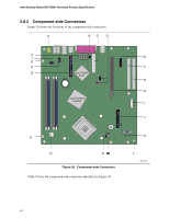
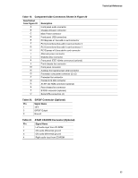
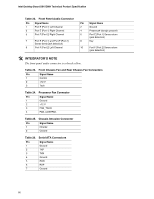
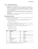
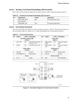
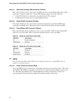
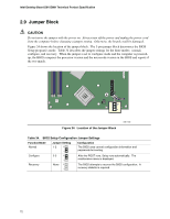
Technical Reference 2.8.2.3 Auxiliary Front Panel Power/Sleep LED Connector Pins 1 and 3 of this connector duplicate the signals on pins 2 and 4 of the front panel connector. Table 30. Auxiliary Front Panel Power/Sleep LED Connector Pin Signal Name 1 HDR_BLNK_GRN 2 Not connected 3 HDR_BLNK_YEL In/Out Out Out Description Front panel green LED Front panel yellow LED 2.8.2.4 Front Panel Connector This section describes the functions of the front panel connector. Table 31 lists the signal names of the front panel connector. Figure 21 is a connection diagram for the front panel connector. Table 31. Front Panel Connector Pin Signal In/Out Description Pin Hard Drive Activity LED [Yellow] 1 HD_PWR Out Hard disk LED pull-up 2 (750 Ω) to +5 V 3 HAD# Out Hard disk active LED 4 Reset Switch [Purple] 5 Ground Ground 6 7 FP_RESET# In Reset switch 8 Power 9 +5 V Power 10 Signal In/Out Description Power LED [Green] HDR_BLNK_ Out GRN Front panel green LED HDR_BLNK_ Out YEL Front panel yellow LED On/Off Switch [Red] FPBUT_IN In Power switch Ground Ground Not Connected N/C Not connected N/C Power Switch Dual-colored Power LED + − Single-colored Power LED − + Green Re d 9 87 65 43 21 Yellow Purple +5 V DC Reset Switch − Hard Drive + Activity LED OM17000 Figure 21. Connection Diagram for Front Panel Connector 69
-
 1
1 -
2
-
3
-
4
-
5
-
6
-
7
-
8
-
9
-
10
-
11
-
12
-
13
-
14
-
15
-
16
-
17
-
18
-
19
-
20
-
21
-
22
-
23
-
24
-
25
-
26
-
27
-
28
-
29
-
30
-
31
-
32
-
33
-
34
-
35
-
36
-
37
-
38
-
39
-
40
-
41
-
42
-
43
-
44
-
45
-
46
-
47
-
48
-
49
-
50
-
51
-
52
-
53
-
54
-
55
-
56
-
57
-
58
-
59
-
60
-
61
-
62
-
63
-
 64
64 -
 65
65 -
 66
66 -
 67
67 -
 68
68 -
 69
69 -
 70
70 -
 71
71 -
 72
72 -
 73
73 -
 74
74 -
75
-
76
-
77
-
78
-
79
-
80
-
81
-
82
-
83
-
84
-
85
-
86
-
87
-
88
-
89
-
90
-
91
-
92
-
93
-
94
-
95
-
96
-
97
-
98
-
99
-
100
 |
 |
