Intel D915GMH Product Specification - Page 43
Power Connector, 13.2.2, Fan Connectors
 |
View all Intel D915GMH manuals
Add to My Manuals
Save this manual to your list of manuals |
Page 43 highlights
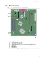
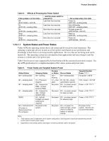
Product Description ✏ NOTE The use of Resume on Ring and Wake from USB technologies from an ACPI state requires an operating system that provides full ACPI support. 1.13.2.1 Power Connector BTX-compliant power supplies can turn off the system power through system control. When an ACPI-enabled system receives the correct command, the power supply removes all non-standby voltages. When resuming from an AC power failure, the computer returns to the power state it was in before power was interrupted (on or off). The computer's response can be set using the Last Power State feature in the BIOS Setup program's Boot menu. For information about The location of the main power connector The signal names of the main power connector Refer to Figure 20, page 64 Table 27, page 67 1.13.2.2 Fan Connectors The function/operation of the fan connectors is as follows: • The fans are on when the board is in the S0 or S1 state. • The fans are off when the board is off or in the S3, S4, or S5 state. • Each fan connector is wired to a fan tachometer input of the hardware monitoring and fan control ASIC. • All fan connectors support closed-loop fan control that can adjust the fan speed or switch the fan on or off as needed. • All fan connectors have a +12 V DC connection. For information about The location of the fan connectors The location of the fan connectors and sensors for thermal monitoring The signal names of the processor fan connector The signal names of the chassis fan connectors Refer to Figure 20, page 64 Figure 15, page 39 Table 24, page 66 Table 23, page 66 43
-
 1
1 -
2
-
3
-
4
-
5
-
6
-
7
-
8
-
9
-
10
-
11
-
12
-
13
-
14
-
15
-
16
-
17
-
18
-
19
-
20
-
21
-
22
-
23
-
24
-
25
-
26
-
27
-
28
-
29
-
30
-
31
-
32
-
33
-
34
-
35
-
36
-
37
-
 38
38 -
 39
39 -
 40
40 -
 41
41 -
 42
42 -
 43
43 -
 44
44 -
 45
45 -
 46
46 -
 47
47 -
 48
48 -
49
-
50
-
51
-
52
-
53
-
54
-
55
-
56
-
57
-
58
-
59
-
60
-
61
-
62
-
63
-
64
-
65
-
66
-
67
-
68
-
69
-
70
-
71
-
72
-
73
-
74
-
75
-
76
-
77
-
78
-
79
-
80
-
81
-
82
-
83
-
84
-
85
-
86
-
87
-
88
-
89
-
90
-
91
-
92
-
93
-
94
-
95
-
96
-
97
-
98
-
99
-
100
 |
 |