Intel D915GMH Product Specification - Page 77
Thermal Considerations
 |
View all Intel D915GMH manuals
Add to My Manuals
Save this manual to your list of manuals |
Page 77 highlights
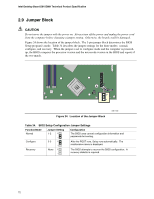
Technical Reference 2.11.4 Power Supply Considerations CAUTION The +5 V standby line for the power supply must be capable of providing adequate +5 V standby current. Failure to do so can damage the power supply. The total amount of standby current required depends on the wake devices supported and manufacturing options. System integrators should refer to the power usage values listed in Table 35 when selecting a power supply for use with the board. Additional power required will depend on configurations chosen by the integrator. 2.12 Thermal Considerations CAUTION A chassis with a maximum internal ambient temperature of 38 oC at the processor fan inlet is a requirement. Failure to provide this could result could result in damage to the board. CAUTION Failure to ensure appropriate airflow may result in reduced performance of both the processor and/or voltage regulator or, in some instances, damage to the board. All responsibility for determining the adequacy of any thermal or system design remains solely with the reader. Intel makes no warranties or representations that merely following the instructions presented in this document will result in a system with adequate thermal performance. CAUTION Ensure that the ambient temperature does not exceed the board's maximum operating temperature. Failure to do so could cause components to exceed their maximum case temperature and malfunction. For information about the maximum operating temperature, see the environmental specifications in Section 2.14. CAUTION Ensure that proper airflow is maintained in the processor voltage regulator circuit. Failure to do so may result in damage to the voltage regulator circuit. Figure 28 shows the locations of the localized high temperature zones. 77
-
 1
1 -
2
-
3
-
4
-
5
-
6
-
7
-
8
-
9
-
10
-
11
-
12
-
13
-
14
-
15
-
16
-
17
-
18
-
19
-
20
-
21
-
22
-
23
-
24
-
25
-
26
-
27
-
28
-
29
-
30
-
31
-
32
-
33
-
34
-
35
-
36
-
37
-
38
-
39
-
40
-
41
-
42
-
43
-
44
-
45
-
46
-
47
-
48
-
49
-
50
-
51
-
52
-
53
-
54
-
55
-
56
-
57
-
58
-
59
-
60
-
61
-
62
-
63
-
64
-
65
-
66
-
67
-
68
-
69
-
70
-
71
-
 72
72 -
 73
73 -
 74
74 -
 75
75 -
 76
76 -
 77
77 -
 78
78 -
 79
79 -
 80
80 -
 81
81 -
 82
82 -
83
-
84
-
85
-
86
-
87
-
88
-
89
-
90
-
91
-
92
-
93
-
94
-
95
-
96
-
97
-
98
-
99
-
100
 |
 |