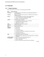
Intel D915GMH Product Specification - Page 7
Error Messages and Beep Codes, s - bios update
 |
View all Intel D915GMH manuals
Add to My Manuals
Save this manual to your list of manuals |
Page 7 highlights
Contents 3.6 BIOS Updates ...88 3.6.1 Language Support 88 3.6.2 Custom Splash Screen 88 3.7 Boot Options ...89 3.7.1 CD-ROM Boot 89 3.7.2 Network Boot 89 3.7.3 Booting Without Attached Devices 89 3.7.4 Changing the Default Boot Device During POST 89 3.8 Fast Booting Systems with Intel® Rapid BIOS Boot 90 3.8.1 Peripheral Selection and Configuration 90 3.8.2 Intel Rapid BIOS Boot 90 3.9 BIOS Security Features 91 4 Error Messages and Beep Codes 4.1 BIOS Error Messages 93 4.2 Port 80h POST Codes 95 4.3 Bus Initialization Checkpoints 99 4.4 Speaker...100 4.5 BIOS Beep Codes...100 Figures 1. Board Components ...14 2. Block Diagram...16 3. Memory Channel Configuration 20 4. Dual Channel (Interleaved) Mode Configuration with Two DIMMs 21 5. Dual Channel (Interleaved) Mode Configuration with Three DIMMs 21 6. Dual Channel (Interleaved) Mode Configuration with Four DIMMs 22 7. Single Channel (Asymmetric) Mode Configuration with One DIMM 23 8. Single Channel (Asymmetric) Mode Configuration with Three DIMMs 23 9. Front/Back Panel Audio Connector Options for 8-Channel (7.1) Audio Subsystem .... 32 10. 8-channel (7.1) Audio Subsystem Block Diagram 33 11. Front/Back Panel Audio Connector Options for 6-Channel (5.1) Audio Subsystem .... 34 12. 6-Channel (5.1) Audio Subsystem Block Diagram 34 13. LAN Connector LED Locations 35 14. LAN Connector LED Locations 36 15. Thermal Monitoring ...39 16. Location of the Standby Power Indicator LED 45 17. Detailed System Memory Address Map 54 18. Back Panel Connectors for 8-Channel (7.1) Audio Subsystem 61 19. Back Panel Connectors for 6-Channel (5.1) Audio Subsystem 62 20. Component-side Connectors 64 21. Connection Diagram for Front Panel Connector 69 22. Connection Diagram for Front Panel USB Connectors 71 23. Connection Diagram for IEEE 1394a Connectors 71 24. Location of the Jumper Block 72 25. Board Dimensions...73 26. I/O Shield Dimensions for Boards with the 8-channel (7.1) Audio Subsystem 74 vii
-
 1
1 -
 2
2 -
 3
3 -
 4
4 -
 5
5 -
 6
6 -
 7
7 -
 8
8 -
 9
9 -
 10
10 -
 11
11 -
 12
12 -
13
-
14
-
15
-
16
-
17
-
18
-
19
-
20
-
21
-
22
-
23
-
24
-
25
-
26
-
27
-
28
-
29
-
30
-
31
-
32
-
33
-
34
-
35
-
36
-
37
-
38
-
39
-
40
-
41
-
42
-
43
-
44
-
45
-
46
-
47
-
48
-
49
-
50
-
51
-
52
-
53
-
54
-
55
-
56
-
57
-
58
-
59
-
60
-
61
-
62
-
63
-
64
-
65
-
66
-
67
-
68
-
69
-
70
-
71
-
72
-
73
-
74
-
75
-
76
-
77
-
78
-
79
-
80
-
81
-
82
-
83
-
84
-
85
-
86
-
87
-
88
-
89
-
90
-
91
-
92
-
93
-
94
-
95
-
96
-
97
-
98
-
99
-
100
 |
 |