Intel D915GMH Product Specification - Page 61
Back Panel Connectors For 8-Channel 7.1 Audio Subsystem
 |
View all Intel D915GMH manuals
Add to My Manuals
Save this manual to your list of manuals |
Page 61 highlights
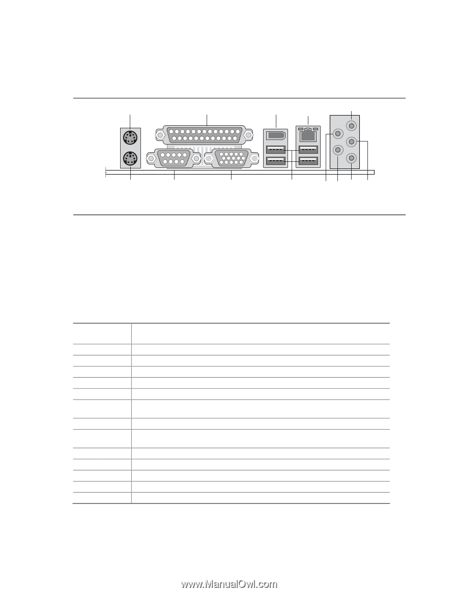
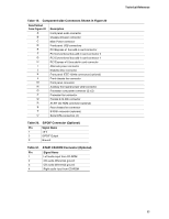
Technical Reference 2.8.1.1 Back Panel Connectors For 8-Channel (7.1) Audio Subsystem Figure 18 shows the location of the back panel connectors for boards equipped with the 8-channel (7.1) audio subsystem. A B C D E M L K J I HG F OM17329 Figure 18. Back Panel Connectors for 8-Channel (7.1) Audio Subsystem Table 17 lists the back panel connectors identified in Figure 18. ✏ NOTE The back panel audio line out connector is designed to power headphones or amplified speakers only. Poor audio quality occurs if passive (non-amplified) speakers are connected to this output. Table 17. Back Panel Connectors Shown in Figure 18 Item/callout from Figure 18 A B C D E F G H I J K L M Description PS/2 mouse port [Green] Parallel port [Burgundy] IEEE-1394a connector (optional) LAN Audio line in/Retasking Jack C [Blue] Front left/right channel audio out/Two channel audio line out/Retasking Jack D [Lime green] Mic in/Retasking Jack B [Pink] Center channel and LFE (subwoofer) audio out/ Retasking Jack G [Orange] Surround left/right channel audio out/Retasking Jack H [Black] USB ports (four) VGA port [Blue] Serial port A [Teal] PS/2 keyboard port [Purple] 61
-
 1
1 -
2
-
3
-
4
-
5
-
6
-
7
-
8
-
9
-
10
-
11
-
12
-
13
-
14
-
15
-
16
-
17
-
18
-
19
-
20
-
21
-
22
-
23
-
24
-
25
-
26
-
27
-
28
-
29
-
30
-
31
-
32
-
33
-
34
-
35
-
36
-
37
-
38
-
39
-
40
-
41
-
42
-
43
-
44
-
45
-
46
-
47
-
48
-
49
-
50
-
51
-
52
-
53
-
54
-
55
-
 56
56 -
 57
57 -
 58
58 -
 59
59 -
 60
60 -
 61
61 -
 62
62 -
 63
63 -
 64
64 -
 65
65 -
 66
66 -
67
-
68
-
69
-
70
-
71
-
72
-
73
-
74
-
75
-
76
-
77
-
78
-
79
-
80
-
81
-
82
-
83
-
84
-
85
-
86
-
87
-
88
-
89
-
90
-
91
-
92
-
93
-
94
-
95
-
96
-
97
-
98
-
99
-
100
 |
 |