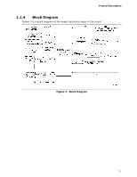
Intel DN2820FYK Technical Product Specification - Page 22
SATA Interface, Real-Time Clock Subsystem - bios update
 |
View all Intel DN2820FYK manuals
Add to My Manuals
Save this manual to your list of manuals |
Page 22 highlights
Intel NUC Board DN2820FY Technical Product Specification 1.6 SATA Interface The SoC provides one SATA port with a theoretical maximum transfer rate of 3 Gb/s. A point-to-point interface is used for host to device connections. The underlying SATA functionality is transparent to the operating system. The SATA controller can operate in both legacy and native modes. In legacy mode, standard IDE I/O and IRQ resources are assigned (IRQ 14 and 15). In Native mode, standard PCI Conventional bus resource steering is used. Native mode is the preferred mode for configurations using Windows operating systems. 1.6.1 AHCI Mode The board supports AHCI storage mode. NOTE In order to use AHCI mode, AHCI must be enabled in the BIOS. Microsoft* Windows 8 includes the necessary AHCI drivers without the need to install separate AHCI drivers during the operating system installation process. However, it is always good practice to update the AHCI drivers to the latest available by Intel. 1.7 Real-Time Clock Subsystem A coin-cell battery (CR2032) powers the real-time clock and CMOS memory. When the computer is not plugged into a wall socket, the battery has an estimated life of three years. When the computer is plugged in, the standby current from the power supply extends the life of the battery. The clock is accurate to ± 13 minutes/year at 25 ºC with 3.3 VSB applied via the power supply 5 V STBY rail. NOTE If the battery and AC power fail, date and time values will be reset and the user will be notified during the POST. When the voltage drops below a certain level, the BIOS Setup program settings stored in CMOS RAM (for example, the date and time) might not be accurate. Replace the battery with an equivalent one. Figure 1 on page 13 shows the location of the battery. 22
-
 1
1 -
2
-
3
-
4
-
5
-
6
-
7
-
8
-
9
-
10
-
11
-
12
-
13
-
14
-
15
-
16
-
 17
17 -
 18
18 -
 19
19 -
 20
20 -
 21
21 -
 22
22 -
 23
23 -
 24
24 -
 25
25 -
 26
26 -
 27
27 -
28
-
29
-
30
-
31
-
32
-
33
-
34
-
35
-
36
-
37
-
38
-
39
-
40
-
41
-
42
-
43
-
44
-
45
-
46
-
47
-
48
-
49
-
50
-
51
-
52
-
53
-
54
-
55
-
56
-
57
-
58
-
59
-
60
-
61
-
62
-
63
-
64
-
65
-
66
-
67
-
68
 |
 |