Intel DN2820FYK Technical Product Specification - Page 9
s, Tables
 |
View all Intel DN2820FYK manuals
Add to My Manuals
Save this manual to your list of manuals |
Page 9 highlights
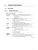
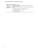
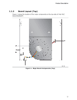
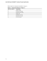
Contents Figures 1. Major Board Components (Top 13 2. Major Board Components (Bottom 15 3. Block Diagram 17 4. Memory Channel and SO-DIMM Configuration 20 5. LAN Connector LED Locations 25 6. Thermal Solution and Fan Header 27 7. Location of the Standby Power LED 32 8. Front Panel Connector 34 9. Back Panel Connectors 35 10. Connectors and Headers (Bottom 36 11. Location of the CIR Sensor 39 12. Location of the BIOS Security Jumper 40 13. Board Dimensions 42 14. Localized High Temperature Zones 44 Tables 1. Feature Summary 11 2. Components Shown in Figure 1 14 3. Components Shown in Figure 2 16 4. Supported Memory Configurations 19 5. LAN Connector LED States 25 6. Effects of Pressing the Power Switch 28 7. Power States and Targeted System Power 29 8. Wake-up Devices and Events 30 9. Connectors and Headers Shown in Figure 10 37 10. PCI Express Half-Mini Card Connector 38 11. BIOS Security Jumper Settings 41 12. Fan Header Current Capability 43 13. Thermal Considerations for Components 45 14. Tcontrol Values for Components 45 15. Environmental Specifications 46 16. Acceptable Drives/Media Types for BIOS Recovery 50 17. Boot Device Menu Options 51 18. Master Key and User Hard Drive Password Functions 53 19. Supervisor and User Password Functions 54 20. Front-panel Power LED Blink Codes 55 21. BIOS Error Messages 55 22. Safety Standards 57 23. EMC Regulations 59 24. Regulatory Compliance Marks 63 ix
-
 1
1 -
2
-
3
-
 4
4 -
 5
5 -
 6
6 -
 7
7 -
 8
8 -
 9
9 -
 10
10 -
 11
11 -
 12
12 -
 13
13 -
 14
14 -
15
-
16
-
17
-
18
-
19
-
20
-
21
-
22
-
23
-
24
-
25
-
26
-
27
-
28
-
29
-
30
-
31
-
32
-
33
-
34
-
35
-
36
-
37
-
38
-
39
-
40
-
41
-
42
-
43
-
44
-
45
-
46
-
47
-
48
-
49
-
50
-
51
-
52
-
53
-
54
-
55
-
56
-
57
-
58
-
59
-
60
-
61
-
62
-
63
-
64
-
65
-
66
-
67
-
68
 |
 |
