Intel DN2820FYK Technical Product Specification - Page 43
Electrical Considerations, Thermal Considerations
 |
View all Intel DN2820FYK manuals
Add to My Manuals
Save this manual to your list of manuals |
Page 43 highlights
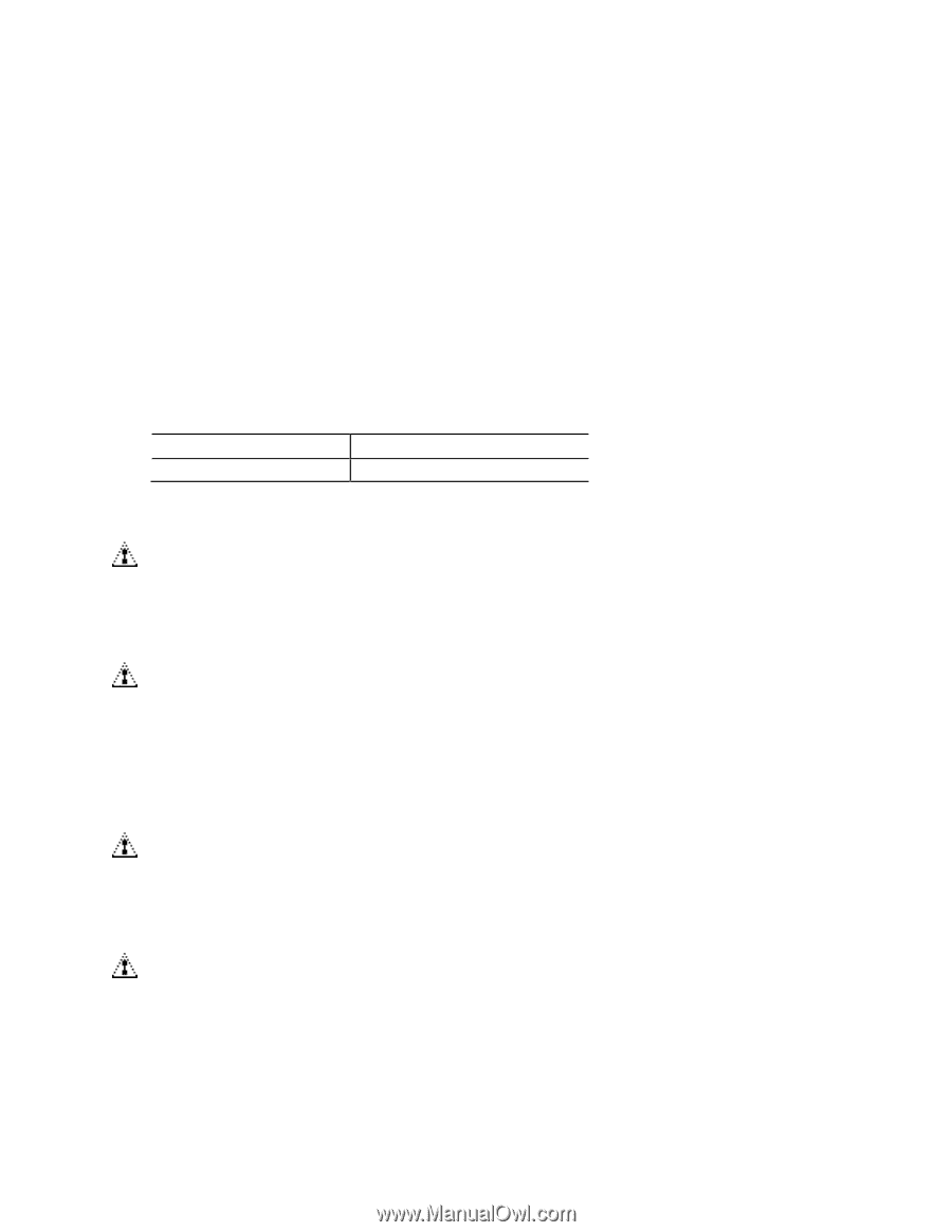
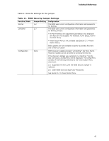
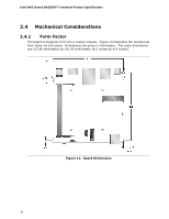
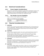
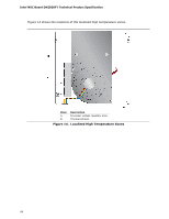
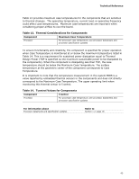
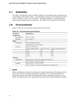
Technical Reference 2.5 Electrical Considerations 2.5.1 Power Supply Considerations System power requirements will depend on actual system configurations chosen by the integrator, as well as end user expansion preferences. It is the system integrator's responsibility to ensure an appropriate power budget for the system configuration is properly assessed based on the system-level components chosen. 2.5.2 Fan Header Current Capability Table 12 lists the current capability of the fan header. Table 12. Fan Header Current Capability Fan Header Maximum Available Current Processor fan .25 A 2.6 Thermal Considerations CAUTION A chassis with a maximum internal ambient temperature of 50 oC at the processor fan inlet is a requirement. Whenever possible, use of a processor heat sink that provides omni-directional airflow to maintain required airflow across the processor voltage regulator area is recommended. CAUTION Failure to ensure appropriate airflow may result in reduced performance of both the processor and/or voltage regulator or, in some instances, damage to the board. All responsibility for determining the adequacy of any thermal or system design remains solely with the system integrator. Intel makes no warranties or representations that merely following the instructions presented in this document will result in a system with adequate thermal performance. CAUTION Ensure that the ambient temperature does not exceed the board's maximum operating temperature. Failure to do so could cause components to exceed their maximum case temperature and malfunction. For information about the maximum operating temperature, see the environmental specifications in Section 2.8. CAUTION The processor voltage regulator area (shown in Figure 14) can reach a temperature of up to 97.5 oC in an open chassis. Ensure that proper airflow is maintained in the processor voltage regulator circuit. Failure to do so may result in shorter than expected product lifetime. 43
-
 1
1 -
2
-
3
-
4
-
5
-
6
-
7
-
8
-
9
-
10
-
11
-
12
-
13
-
14
-
15
-
16
-
17
-
18
-
19
-
20
-
21
-
22
-
23
-
24
-
25
-
26
-
27
-
28
-
29
-
30
-
31
-
32
-
33
-
34
-
35
-
36
-
37
-
 38
38 -
 39
39 -
 40
40 -
 41
41 -
 42
42 -
 43
43 -
 44
44 -
 45
45 -
 46
46 -
 47
47 -
 48
48 -
49
-
50
-
51
-
52
-
53
-
54
-
55
-
56
-
57
-
58
-
59
-
60
-
61
-
62
-
63
-
64
-
65
-
66
-
67
-
68
 |
 |