Intel DQ965WC Product Specification
Intel DQ965WC Manual
 |
View all Intel DQ965WC manuals
Add to My Manuals
Save this manual to your list of manuals |
Intel DQ965WC manual content summary:
- Intel DQ965WC | Product Specification - Page 1
September 2006 Order Number: D56018-001US The Intel® Desktop Board DQ965WC may contain design defects or errors known as errata that may cause the product to deviate from published specifications. Current characterized errata are documented in the Intel Desktop Board DQ965WC Specification Update. - Intel DQ965WC | Product Specification - Page 2
Intel® Desktop Board DQ965WC with BIOS identifier CO96510J.86A. Changes to this specification will be published in the Intel Desktop Board DQ965WC other Countries 708-296-9333. Intel, the Intel logo, Pentium, and Celeron are registered trademarks of Intel Corporation or its subsidiaries in the United - Intel DQ965WC | Product Specification - Page 3
power and environmental requirements, and the BIOS for the Intel® Desktop Board DQ965WC. It describes the standard product and available manufacturing options. Intended Audience The TPS is intended to provide detailed, technical information about the Desktop Board DQ965WC and its components to the - Intel DQ965WC | Product Specification - Page 4
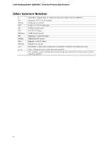
Intel Desktop Board DQ965WC Technical Product Specification Other Common Notation # GB GB/sec Gbit KB Kbit kbits/sec MB MB/sec Mbit Mbit/sec xxh x.x V * Used after a signal name - Intel DQ965WC | Product Specification - Page 5
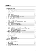
10 1.1.1 Feature Summary 10 1.1.2 Board Layout 12 1.1.3 Block Diagram 14 1.2 Online Support 15 1.3 Processor 15 1.4 System Memory 16 1.4.1 Memory Configurations 18 1.5 Intel® Virtualization Technology (Intel® VT 23 1.6 Intel® vPro™ Technology Support 24 1.7 Intel® Q965 Express Chipset 25 - Intel DQ965WC | Product Specification - Page 6
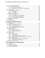
Intel Desktop Board DQ965WC Technical Product Specification 2.6 PCI Interrupt Routing Map 51 2.7 Connectors and Headers 52 72 3.4 System Management BIOS (SMBIOS 73 3.5 Legacy USB Support 73 3.6 BIOS Updates 74 3.6.1 Language Support 74 3.6.2 Custom Splash Screen 74 3.7 BIOS Recovery 75 3.8 - Intel DQ965WC | Product Specification - Page 7
60 20. Location of the Jumper Block 61 21. Board Dimensions 62 22. I/O Shield Dimensions 63 23. Localized High Temperature Zones 67 Tables 1. Feature Summary 10 2. Board Components Shown in Figure 1 13 3. Supported Memory Configurations 16 4. Memory Operating Frequencies 17 5. DVI Port - Intel DQ965WC | Product Specification - Page 8
Intel Desktop Board DQ965WC Audio Header 56 24. Processor Core Power Connector 57 25. Main Power Connector 57 26. Front Desktop Board DQ965WC Environmental Specifications 69 35. BIOS Setup Program Menu Bar 72 36. BIOS Setup Program Function Keys 72 37. Acceptable Drives/Media Types for BIOS - Intel DQ965WC | Product Specification - Page 9
1 Product Description What This Chapter Contains 1.1 Overview 10 1.2 Online Support 15 1.3 Processor 15 1.4 System Memory 16 1.5 Intel® Virtualization Technology 23 1.6 Intel® vPro™ Technology Support 24 1.7 Intel® Q965 Express Chipset 25 1.8 Audio Subsystem 30 1.9 LAN Subsystem 32 1.10 - Intel DQ965WC | Product Specification - Page 10
LAN Support BIOS Trusted Platform Module (TPM), revision 1.2 picoBTX Form Factor (8.00 inches by 10.50 inches [203.20 millimeters by 266.70 millimeters]) Support for the following: • Intel® Core™2 Duo processor in an LGA775 socket with a 1066 or 800 MHz system bus • Intel® Pentium® D processor in - Intel DQ965WC | Product Specification - Page 11
ports Expansion Capabilities Hardware Monitor Subsystem Intel® vPro™ Technology support One PCI Express x16 bus add-in card connector • Intel® Quiet System Technology implemented through the information about Available configurations for the Desktop Board DQ965WC Refer to Section 1.2, page 15 11 - Intel DQ965WC | Product Specification - Page 12
Intel Desktop Board DQ965WC Technical Product Specification 1.1.2 Board Layout Figure 1 shows the location of the major components. Figure 1. Major Board Components Table 2 lists the components identified in Figure 1. 12 - Intel DQ965WC | Product Specification - Page 13
Hub (ICH8DO) J BIOS Setup configuration jumper block K Chassis intrusion header L Front panel header M Auxiliary front panel power LED header N Processor fan header O LGA775 processor socket P Intel 82Q965 GMCH Q DIMM Channel A sockets R Processor core power connector S Speaker - Intel DQ965WC | Product Specification - Page 14
Intel Desktop Board DQ965WC Technical Product Specification 1.1.3 Block Diagram Figure 2 is a block diagram of the major functional areas. Gigabit Ethernet Controller LAN Connector LGA775 Processor Socket System Bus (1066/800/533 MHz) PCI Express x16 Connector PCI Express x16 Interface Display - Intel DQ965WC | Product Specification - Page 15
The board is designed to support the following processors: • Intel Core 2 Duo processor in an LGA775 socket with a 1066 or 800 MHz system bus • Intel Pentium D processor in an LGA775 processor socket with an 800 or 533 MHz system bus • Intel Pentium 4 processor in an LGA775 processor socket with - Intel DQ965WC | Product Specification - Page 16
Intel Desktop Board DQ965WC Technical Product Specification 1.4 System Memory The board has four DIMM sockets and supports the following memory features: • , the board should be populated with DIMMs that support the Serial Presence Detect (SPD) data structure. This enables the BIOS to read - Intel DQ965WC | Product Specification - Page 17
memory will operate at 533 MHz. Table 4 lists the resulting operating memory frequencies based on the combination of DIMMs and processors. Table 4. Memory Operating Frequencies DIMM Type Processor system bus frequency DDR2 533 DDR2 533 DDR2 533 DDR2 667 DDR2 667 DDR2 667 DDR2 800 DDR2 800 DDR2 - Intel DQ965WC | Product Specification - Page 18
Intel Desktop Board DQ965WC Technical Product Specification 1.4.1 Memory Configurations The Intel 82Q965 GMCH supports the following types the memory channel and DIMM configuration. NOTE The DIMM0 sockets of both channels are blue. The DIMM1 sockets of both channels are black. Channel A, DIMM 0 - Intel DQ965WC | Product Specification - Page 19
DIMMs. In this example, the combined capacity of the two DIMMs in Channel A equal the capacity of the single DIMM in the DIMM0 (blue) socket of Channel B. 256 MB 256 MB 512 MB Channel A, DIMM 0 Channel A, DIMM 1 Channel B, DIMM 0 Channel B, DIMM 1 OM18358 Figure 5. Dual Channel (Interleaved) Mode - Intel DQ965WC | Product Specification - Page 20
Intel Desktop Board DQ965WC Technical Product Specification Figure 6 shows a dual channel configuration using four DIMMs. In this example, the combined capacity of the two DIMMs in Channel A equal the - Intel DQ965WC | Product Specification - Page 21
this example, the combined capacity of the two DIMMs in Channel A does not equal the capacity of the single DIMM in the DIMM0 (blue) socket of Channel B. 256 MB 512 MB 512 MB Channel A, DIMM 0 Channel A, DIMM 1 Channel B, DIMM 0 Channel B, DIMM 1 OM18361 Figure 8. Single Channel (Asymmetric) Mode - Intel DQ965WC | Product Specification - Page 22
Desktop Board DQ965WC Technical Product Specification 1.4.1.3 Flex Mode Configuration NOTE The use of flex mode requires DIMMs to be installed in both channels. Figure 9 shows a flex mode configuration using two DIMMs. The operation is as follows: • The 512 MB DIMM in the Channel A, DIMM 0 socket - Intel DQ965WC | Product Specification - Page 23
processors, memory, storage, and network adapters can be allocated and prioritized for the different partitions to meet specific business and application requirements. Intel® Virtualization Technology (Intel® VT) offers silicon-level support for core Intel® network adapter and compatible driver - Intel DQ965WC | Product Specification - Page 24
applications. # INTEGRATOR'S NOTE In addition to the hardware support on the board (the Intel 82801HO ICH8DO and the Intel 82566DM Gigabit Ethernet Controller), Intel vPro technology requires the use of an Intel Core 2 Duo processor and compatible third-party applications. For information about - Intel DQ965WC | Product Specification - Page 25
interfaces to the CPU, memory, PCI Express, and the DMI interconnect. The component also provides integrated graphics capabilities supporting 3D, 2D and display capabilities. The ICH8DO is a centralized controller for the board's I/O paths. For information about The Intel Q965 Express chipset - Intel DQ965WC | Product Specification - Page 26
Intel Desktop Board DQ965WC Technical Product Specification ⎯ Maximum 3D supported resolution of 1600 x 1200 x 32 at 85 Hz ⎯ Vertex cache ⎯ Anti-aliased lines ⎯ OpenGL version 1.5 support support ⎯ Supports TMDS transmitters or TV-out encoders ⎯ HDCP support support up to 256 MB • Intel the BIOS Setup - Intel DQ965WC | Product Specification - Page 27
use of DVMT requires operating system driver support. 1.7.1.3 Configuration Modes A list of supported modes for the Intel GMA 3000 graphics controller is available as a downloadable document. For information about Supported video modes for the board Refer to Section 1.2, page 15 1.7.1.4 Digital - Intel DQ965WC | Product Specification - Page 28
Intel Desktop Board DQ965WC Technical Product Specification 1.7.2 USB The board supports up to 10 USB 2.0 ports, supports UHCI and EHCI, and uses UHCIand EHCI-compatible drivers is the preferred mode for configurations using the Windows* XP and Windows 2000 operating systems. NOTE Many Serial ATA - Intel DQ965WC | Product Specification - Page 29
Serial ATA RAID The ICH8DO supports the following RAID (Redundant Array memory. When the computer is not plugged into a wall socket, the battery has an estimated life of three years. . When the voltage drops below a certain level, the BIOS Setup program settings stored in CMOS RAM (for example, - Intel DQ965WC | Product Specification - Page 30
Intel Desktop Board DQ965WC Technical Product Specification 1.8 Audio Subsystem The onboard audio subsystem consists of the following: • Intel 82801HO ICH8DO • Sigmatel STAC9227 audio codec • Back panel audio connectors • Component-side audio headers: ⎯ Front panel audio header ⎯ HD audio link - Intel DQ965WC | Product Specification - Page 31
of the board. The front panel audio header provides mic in and line out signals for the front panel. Microphone bias is supported for both the front and back panel microphone connectors. The front/back panel audio connectors are configurable through the audio device drivers. - Intel DQ965WC | Product Specification - Page 32
Intel Desktop Board DQ965WC Technical Product Specification 1.9 LAN Subsystem The LAN subsystem consists of the following: • Intel 82566DM Gigabit (10/100/1000 Mbits/sec) Ethernet LAN controller • Intel 82801HO ICH8DO • RJ-45 LAN connector with integrated status LEDs Additional features of the LAN - Intel DQ965WC | Product Specification - Page 33
LED Locations Table 7 describes the LED states when the board is powered up and the LAN subsystem is operating. Table Intel AMT include: • Secure Out of Band (OOB) system management that allows remote management of PCs regardless of system power or operating system state. • Remote troubleshooting - Intel DQ965WC | Product Specification - Page 34
to http://www.intel.com/technology/manage/iamt/index.htm 1.9.5 Alert Standard Format (ASF) 2.0 Support The board provides the following ASF support for PCI Express x1 bus add-in LAN cards: • Monitoring of system firmware progress events, including: ⎯ BIOS present ⎯ Primary processor initialization - Intel DQ965WC | Product Specification - Page 35
Intel Quiet System Technology, delivering acoustically-optimized thermal management • Fan speed control controllers and sensors integrated into the ICH8DO • Four thermal sensors (processor can be implemented using Intel Desktop Utilities or third-party and Detection The board supports a chassis - Intel DQ965WC | Product Specification - Page 36
Intel Desktop Board DQ965WC Technical Product Specification 1.10.4 Thermal Monitoring Figure 12 shows the locations of the thermal sensors and fan headers. Item A B C D E F G Description Thermal diode, located on processor die Thermal diode, located on the GMCH die Thermal diode, located on the - Intel DQ965WC | Product Specification - Page 37
an operating system that provides full ACPI support. ACPI features include: • Plug and Play (including bus and device enumeration) • Power management control of individual devices, add-in boards (some add-in boards may require an ACPI-aware driver), video displays, and hard disk drives • Methods - Intel DQ965WC | Product Specification - Page 38
Intel Desktop Board DQ965WC low-power state. Table 9 lists the power states supported by the board along with the associated system power targets. See the ACPI system. Service can be performed safely. Notes: 1. Total system power is dependent on the system configuration, including add-in boards and - Intel DQ965WC | Product Specification - Page 39
for appliances and personal computers. This board meets that requirement by operating at For LAN, S5 is disabled by default in the BIOS Setup program. Setting this option to Power On support. In addition, software, drivers, and peripherals must fully support ACPI wake events. 1.11.2 Hardware Support - Intel DQ965WC | Product Specification - Page 40
Intel Desktop Board DQ965WC Technical Product Specification • Resume on Ring • Wake from USB • WAKE# signal wake-up support LAN State feature in the BIOS Setup program's Boot menu. For information about The location of the main power connector The signal names of the main power connector Refer to - Intel DQ965WC | Product Specification - Page 41
Interface Specification. Add-in boards that also support this specification can participate in power management and can be used to wake the computer. The use of Instantly Available PC technology requires operating system support and PCI 2.3 compliant add-in cards and drivers. 1.11.2.5 Resume on Ring - Intel DQ965WC | Product Specification - Page 42
Intel Desktop Board DQ965WC Technical Product Specification 1.11.2.6 Wake from USB USB bus activity wakes the computer from ACPI S3 state. NOTE Wake from USB requires the use of a USB peripheral that supports Wake from USB. 1.11.2.7 WAKE# Signal Wake-up Support memory and the board. Before installing - Intel DQ965WC | Product Specification - Page 43
Product Description Item A B Description +5 V standby power indicator LED Memory power indicator LED LED color Green Red Figure 13. Location of the Onboard Power Indicator LEDs 43 - Intel DQ965WC | Product Specification - Page 44
Intel Desktop Board DQ965WC Technical Product Specification 1.12 Trusted Platform Module (TPM) The TPM 1.2 component is specifically designed to platform authentication information from software-based attacks. For information about TPM 1.2 Refer to http://www.intel.com/design/motherbd/wc/ 44 - Intel DQ965WC | Product Specification - Page 45
69 2.1 Memory Map 2.1.1 Addressable Memory The board utilizes 8 GB of addressable system memory. Typically PCI Conventional bus add-in cards, PCI Express configuration space, BIOS (SPI Flash), and chipset overhead resides above the top of support (6 MB) • Base graphics memory support (1 MB or 8 MB) 45 - Intel DQ965WC | Product Specification - Page 46
Intel Desktop Board DQ965WC Technical Product Specification The amount of installed memory that can be used will vary based on add-in cards and BIOS settings. Figure 14 shows a schematic of the system memory map. All installed system memory can be used when there is no overlap of system addresses. - Intel DQ965WC | Product Specification - Page 47
Reserved Potential available high DOS memory (open to the PCI bus). Dependent on video adapter used. Video memory and BIOS Extended BIOS data (movable by memory manager software) Extended conventional memory Conventional memory System Resource Open Open Open Open DMA controller Open Open Open 47 - Intel DQ965WC | Product Specification - Page 48
bytes 8 bytes 8 bytes 2 bytes 8 bytes 4 bytes 1 byte 4 bytes Description Used by the Desktop Board DQ965WC. Refer to the ICH8DO data sheet for dynamic addressing information. LPT3 LPT2 COM4 COM2 LPT1 Intel 82Q965 GMCH Intel 82Q965 GMCH COM3 COM1 Edge/level triggered PIC ECP port, LPTn base address - Intel DQ965WC | Product Specification - Page 49
Number (hex) Number (hex) Description 00 00 00 Memory controller of Intel 82Q965 component 00 01 00 PCI Express x16 graphics port (Note 1) 00 02 00 Integrated graphics controller 00 1B 00 Intel High Definition Audio Controller 00 1D 00 USB UHCI controller 1 00 1D - Intel DQ965WC | Product Specification - Page 50
Intel Desktop Board DQ965WC Technical Product Specification 2.5 Interrupts The interrupts can be routed through either the Programmable Interrupt Controller (PIC) or the Advanced Programmable Interrupt Controller (APIC) portion of the ICH8DO component. The PIC is supported in Windows 98 SE and - Intel DQ965WC | Product Specification - Page 51
either onboard or from a PCI add-in card connect to one of these PIRQ signals. Some PCI interrupt sources are electrically tied together on the board and therefore share the same interrupt. Table 16 shows an example of how the PIRQ signals are routed. Table 16. PCI Interrupt Routing Map PCI - Intel DQ965WC | Product Specification - Page 52
Intel Desktop Board DQ965WC Technical Product Specification 2.7 Connectors and Headers CAUTION Only the to the computer, the power cable, and the external devices themselves. This section describes the board's connectors and headers. The connectors and headers can be divided into these groups: • Back - Intel DQ965WC | Product Specification - Page 53
Technical Reference 2.7.1 Back Panel Connectors Figure 15 shows the locations of the back panel connectors. A E F H B C D G Item A B C D E F G H I J Description VGA port DVI-D connector (digital output only) USB ports [2] USB ports [2] IEEE-1394a LAN USB ports [2] Audio line in Mic in - Intel DQ965WC | Product Specification - Page 54
Intel Desktop Board DQ965WC Technical Product Specification 2.7.2 Component-side Connectors and Headers Figure 16 shows the locations of the component-side connectors and headers. Figure 16. Component-side Connectors and Headers 54 - Intel DQ965WC | Product Specification - Page 55
PCI Express x16 add-in card connector E Front chassis fan header F Main power connector G Auxiliary front panel power LED header H Front panel header I Processor fan connector J Processor core power connector K Chassis intrusion header L Serial ATA connectors [4] M Rear chassis fan - Intel DQ965WC | Product Specification - Page 56
Intel Desktop Board DQ965WC Technical Product Specification Table 21. Serial ATA Connectors Pin Signal Name 1 Ground 2 TXP 3 TXN 4 Ground 5 RXN 6 RXP 7 Ground Table 22. High Definition Audio Link Header - Intel DQ965WC | Product Specification - Page 57
. This connector is compatible with 2 x 10 connectors previously used on Intel Desktop boards. The board supports the use of ATX12V power supplies with either 2 x 10 or 2 x 12 main power cables. When using a power supply with a 2 x 10 main power cable, attach that cable on the rightmost pins of the - Intel DQ965WC | Product Specification - Page 58
Intel Desktop Board DQ965WC Technical Product Specification 2.7.2.3 Front Panel Header This section describes the functions of the front panel header. Table 26 lists the signal names of the front - Intel DQ965WC | Product Specification - Page 59
(SPST) type switch that is normally open. When the switch is closed, the board resets and runs the POST. 2.7.2.3.3 Power/Sleep LED Header Pins 2 and 4 . (The time requirement is due to internal debounce circuitry on the board.) At least two seconds must pass before the power supply will recognize - Intel DQ965WC | Product Specification - Page 60
Intel Desktop Board DQ965WC Technical Product Specification 2.7.2.5 Front Panel USB Headers Figure 18 is a connection diagram for the front panel USB headers. # INTEGRATOR'S NOTES • The +5 V DC power on the - Intel DQ965WC | Product Specification - Page 61
setting. Otherwise, the board could be damaged. Figure 20 shows the location of the jumper block. The jumper determines the BIOS Setup program's mode and the computer is powered-up, the BIOS compares the processor version and the microcode version in the BIOS and reports if the two match. Figure 20 - Intel DQ965WC | Product Specification - Page 62
Intel Desktop Board DQ965WC Technical Product Specification 2.9 Mechanical Considerations 2.9.1 Form Factor The board is designed to fit into a BTX-form-factor chassis. Figure 21 illustrates the mechanical form factor of the board. Dimensions are given in inches [millimeters]. The outer dimensions - Intel DQ965WC | Product Specification - Page 63
I/O shield for the board must meet specific dimension and material requirements. Systems based on this board need the back panel shield drawing is for reference only. I/O shields compliant with the BTX specification are available from Intel. 172.93 REF [6.808] 1.00 [0.039] 6.09 [0.0240] 0.00 [0.000] - Intel DQ965WC | Product Specification - Page 64
Intel Desktop Board DQ965WC Technical Product Specification 2.10 Electrical Considerations 2.10.1 DC Loading Table 31 lists the DC loading characteristics of the board. This data is based on a DC analysis of all active components within the board that impact its power delivery subsystems. The - Intel DQ965WC | Product Specification - Page 65
The total amount of standby current required depends on the wake devices supported and manufacturing options. System integrators should refer to the power usage values Table 31 when selecting a power supply for use with the board. Additional power required will depend on configurations chosen by the - Intel DQ965WC | Product Specification - Page 66
Intel Desktop Board DQ965WC Technical Product Specification 2.11 Thermal Considerations CAUTION This board requires the use of a BTX Thermal Module for the processor. Failure to ensure appropriate airflow may result in reduced performance of both the processor and/or voltage regulator or, in some - Intel DQ965WC | Product Specification - Page 67
Technical Reference Item A B C D E Description Intel 82Q965 GMCH Intel 82801HO ICH8DO 1.5 V core and front side bus voltage regulator areas Processor Processor voltage regulator area Figure 23. Localized High Temperature Zones 67 - Intel DQ965WC | Product Specification - Page 68
Intel Desktop Board DQ965WC Technical Product Specification Table 33 provides maximum case temperatures for the board components that are sensitive to thermal changes. The operating temperature, current load, or operating frequency could affect case temperatures. Maximum case temperatures are - Intel DQ965WC | Product Specification - Page 69
Technical Reference 2.13 Environmental Table 34 lists the environmental specifications for the board. Table 34. Desktop Board DQ965WC Environmental Specifications Parameter Specification Temperature Non-Operating -40 °C to +70 °C Operating 0 °C to +55 °C Shock Unpackaged 50 g trapezoidal - Intel DQ965WC | Product Specification - Page 70
Intel Desktop Board DQ965WC Technical Product Specification 70 - Intel DQ965WC | Product Specification - Page 71
72 3.3 Resource Configuration 72 3.4 System Management BIOS (SMBIOS 73 3.5 Legacy USB Support 73 3.6 BIOS Updates 74 3.7 BIOS Recovery 75 3.8 Boot Options 75 3.9 Adjusting Boot Speed 76 3.10 BIOS Security Features 78 3.1 Introduction The board uses an Intel BIOS that is stored in the Serial - Intel DQ965WC | Product Specification - Page 72
Intel Desktop Board DQ965WC Technical Product Specification Table 35 lists the BIOS Setup program menu features. Table 35. BIOS Setup Program Menu Bar Maintenance Main Advanced Security Clears passwords and displays processor information Displays processor and memory configuration Configures - Intel DQ965WC | Product Specification - Page 73
error logging Non-Plug and Play operating systems, such as Windows NT*, require an additional interface for obtaining the SMBIOS information. The BIOS supports an SMBIOS table interface for such operating systems. Using this support, an SMBIOS service-level application running on a non-Plug and Play - Intel DQ965WC | Product Specification - Page 74
Intel Desktop Board DQ965WC Technical Product Specification 3.6 BIOS Updates The BIOS can be updated using either of the following utilities, which are available on the Intel World Wide Web site: • Intel® Express BIOS Update utility, which enables automated updating while in the Windows environment - Intel DQ965WC | Product Specification - Page 75
Yes USB diskette drive (with a 1.44 MB diskette) No USB hard disk drive No For information about BIOS recovery Refer to http://support.intel.com/support/motherboards/desktop 3.8 Boot Options In the BIOS Setup program, the user can choose to boot from a hard drive, CD-ROM, or the network. The - Intel DQ965WC | Product Specification - Page 76
Intel Desktop Board DQ965WC Technical Product Specification 3.8.3 Booting Without Attached Devices For use in embedded applications, the BIOS has been designed so that after passing the POST, the operating system loader is invoked even if the following devices are not present: • Video adapter • - Intel DQ965WC | Product Specification - Page 77
Boot Optimizations Use of the following BIOS Setup program settings reduces the POST execution time. • In is possible to optimize the boot process to the point where the system boots so quickly that the Intel logo screen (or a custom logo splash screen) will not be seen. Monitors and hard disk - Intel DQ965WC | Product Specification - Page 78
Intel Desktop Board DQ965WC Technical Product Specification 3.10 BIOS Security Features The BIOS includes security features that restrict access to the BIOS Setup program and who can boot the computer. A supervisor password and a user password can be set for the BIOS Setup program and for booting - Intel DQ965WC | Product Specification - Page 79
Speaker 79 4.2 BIOS Beep Codes 79 4.3 BIOS Error Messages 79 4.4 Port 80h POST Codes 80 4.1 Speaker The board-mounted speaker provides audible page 12 4.2 BIOS Beep Codes Whenever a recoverable error occurs during POST, the BIOS displays an error message describing the problem (see Table 40 - Intel DQ965WC | Product Specification - Page 80
Intel Desktop Board DQ965WC Technical Product Specification 4.4 Port 80h POST Codes During the POST, the BIOS generates diagnostic - 0F Debug codes: Can be used by any PEIM/driver for debug. 10 - 1F Host Processors: 1F is an unrecoverable CPU error. 20 - 2F Memory/Chipset: 2F is no memory - Intel DQ965WC | Product Specification - Page 81
POST Codes POST Code Description of POST Operation Host Processor 10 Power-on initialization of the host processor (Boot Strap Processor) 11 Host processor Cache initialization (including APs) 12 Starting Application processor initialization 13 SMM initialization Chipset 21 Initializing - Intel DQ965WC | Product Specification - Page 82
Intel Desktop Board DQ965WC Technical Product Enabling the keyboard 94 Clearing keyboard input buffer 95 Instructing keyboard controller to run Self Test (PS2 only) Mouse Dy Trying boot selection y (y=0 to 15) PEI Core E0 Started dispatching PEIMs (emitted on first report of - Intel DQ965WC | Product Specification - Page 83
Code Description of POST Operation DXE Drivers E7 Waiting for user input E8 Checking password E9 Entering BIOS setup EB Calling Legacy Option service ExitBootServices ( ) has been called F9 EFI runtime service SetVirtualAddressMap ( ) has been called FA EFI runtime service ResetSystem - Intel DQ965WC | Product Specification - Page 84
Intel Desktop Board DQ965WC Technical capsule E4 Entered DXE phase 12 Starting Application processor initialization 13 SMM initialization 50 Enumerating PCI Clearing keyboard input buffer 95 Keyboard Self Test EB Calling Video BIOS 58 Resetting USB bus 5A Resetting PATA/SATA bus and - Intel DQ965WC | Product Specification - Page 85
of Conformity statement • Product Ecology statements • Electromagnetic Compatibility (EMC) regulations • Product certification markings 5.1.1 Safety Regulations Desktop Board DQ965WC complies with the safety regulations stated in Table 45 when correctly installed in a compatible host system. Table - Intel DQ965WC | Product Specification - Page 86
Technical Product Specification 5.1.2 European Union Declaration of Conformity Statement We, Intel Corporation, declare under our sole responsibility that the product Intel® Desktop Board DQ965WC is in conformity with all applicable essential requirements necessary for CE marking, following - Intel DQ965WC | Product Specification - Page 87
Regulatory Compliance and Battery Disposal Information Portuguese Este produto cumpre com as normas da Diretiva Européia 89/336/EEC & 73/23/EEC. Español Este producto cumple con las normas del Directivo Europeo 89/336/EEC & 73/23/EEC. Slovensky Tento produkt je v súlade s ustanoveniami európskych - Intel DQ965WC | Product Specification - Page 88
Intel Desktop Board DQ965WC Technical Product Specification 5.1.3 Product Ecology Statements The following information is instructions, terms and conditions, etc Intel Product Recycling Program http://www.intel.com/intel/other/ehs/product_ecology/Recycling_Program.htm Deutsch Als Teil von Intels - Intel DQ965WC | Product Specification - Page 89
en savoir plus sur ce programme, à savoir les produits concernés, les adresses disponibles, les instructions d'expédition, les conditions générales, etc http://www.intel.com/intel /other/ehs/product_ecology/Recycling_Program.htm Malay Sebagai sebahagian daripada komitmennya terhadap tanggungjawab - Intel DQ965WC | Product Specification - Page 90
Intel Desktop Board DQ965WC Technical Product Specification Türkçe Intel, çevre sorumluluğuna bağımlılığının bir parçası olarak, perakende tüketicilerin Intel markalı kullanılmış ürünlerini belirlenmiş merkezlere iade edip uygun şekilde geri dönüştürmesini amaçlayan Intel Ürünleri Geri Dönüşüm - Intel DQ965WC | Product Specification - Page 91
Regulatory Compliance and Battery Disposal Information 5.1.4 EMC Regulations Desktop Board DQ965WC complies with the EMC regulations stated in Table 47 when correctly installed in a environment, it may cause radio interference. Install and use the equipment according to the instruction manual. 91 - Intel DQ965WC | Product Specification - Page 92
for Intel desktop boards: E210882. Mark FCC Declaration of Conformity logo mark for Class B equipment. Includes Intel name and DQ965WC model designation. number: CPU-DQ965WC For information about MIC certification, go to http://support.intel.com/support/motherboards/desktop/ Taiwan BSMI - Intel DQ965WC | Product Specification - Page 93
Regulatory Compliance and Battery Disposal Information 5.2 Battery Disposal Information CAUTION Risk of explosion if the battery is replaced with an incorrect type. Batteries should be recycled where possible. Disposal of used batteries must be in accordance with local environmental regulations. - Intel DQ965WC | Product Specification - Page 94
Intel Desktop Board DQ965WC Technical Product Specification PRECAUCIÓN Existe peligro de explosión si la pila no se cambia de forma adecuada. Utilice solamente pilas iguales o del mismo tipo que - Intel DQ965WC | Product Specification - Page 95
Regulatory Compliance and Battery Disposal Information AWAS Risiko letupan wujud jika bateri digantikan dengan jenis yang tidak betul. Bateri sepatutnya dikitar semula jika boleh. Pelupusan bateri terpakai mestilah mematuhi peraturan alam sekitar tempatan. OSTRZEŻENIE Istnieje niebezpieczeństwo - Intel DQ965WC | Product Specification - Page 96
Intel Desktop Board DQ965WC Technical Product Specification 96
-
 1
1 -
 2
2 -
 3
3 -
 4
4 -
 5
5 -
 6
6 -
 7
7 -
8
-
9
-
10
-
11
-
12
-
13
-
14
-
15
-
16
-
17
-
18
-
19
-
20
-
21
-
22
-
23
-
24
-
25
-
26
-
27
-
28
-
29
-
30
-
31
-
32
-
33
-
34
-
35
-
36
-
37
-
38
-
39
-
40
-
41
-
42
-
43
-
44
-
45
-
46
-
47
-
48
-
49
-
50
-
51
-
52
-
53
-
54
-
55
-
56
-
57
-
58
-
59
-
60
-
61
-
62
-
63
-
64
-
65
-
66
-
67
-
68
-
69
-
70
-
71
-
72
-
73
-
74
-
75
-
76
-
77
-
78
-
79
-
80
-
81
-
82
-
83
-
84
-
85
-
86
-
87
-
88
-
89
-
90
-
91
-
92
-
93
-
94
-
95
-
96
 |
 |

September
2006
Order Number:
D56018-001US
The Intel
®
Desktop Board DQ965WC may contain design defects or errors known as errata that may cause the product to deviate from published specifications.
Current
characterized errata are documented in the Intel Desktop Board DQ965WC Specification Update.
Intel® Desktop Board
DQ965WC
Technical Product Specification