Intel DQ965WC Product Specification - Page 8

Component-side Connectors and Headers Shown - main board

Page 8 highlights

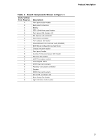
Intel Desktop Board DQ965WC Technical Product Specification 10. Wake-up Devices and Events 39 11. System Memory Map 47 12. DMA Channels 47 13. I/O Map 48 14. PCI Configuration Space Map 49 15. Interrupts 50 16. PCI Interrupt Routing Map 51 17. Component-side Connectors and Headers Shown in Figure 16 55 18. Front and Rear Chassis Fan Headers 55 19. Processor Fan Header 55 20. Chassis Intrusion Header 55 21. Serial ATA Connectors 56 22. High Definition Audio Link Header 56 23. Front Panel Audio Header 56 24. Processor Core Power Connector 57 25. Main Power Connector 57 26. Front Panel Header 58 27. States for a One-Color Power LED 59 28. States for a Two-Color Power LED 59 29. Auxiliary Front Panel Power LED Header 59 30. BIOS Setup Configuration Jumper Settings 61 31. DC Loading Characteristics 64 32. Fan Header Current Capability 64 33. Thermal Considerations for Components 68 34. Desktop Board DQ965WC Environmental Specifications 69 35. BIOS Setup Program Menu Bar 72 36. BIOS Setup Program Function Keys 72 37. Acceptable Drives/Media Types for BIOS Recovery 75 38. Boot Device Menu Options 76 39. Supervisor and User Password Functions 78 40. Beep Codes 79 41. BIOS Error Messages 79 42. Port 80h POST Code Ranges 80 43. Port 80h POST Codes 81 44. Typical Port 80h POST Sequence 84 45. Safety Regulations 85 46. Lead-Free Board Markings 90 47. EMC Regulations 91 48. Product Certification Markings 92 viii

  • 1
  • 2
  • 3
  • 4
  • 5
  • 6
  • 7
  • 8
  • 9
  • 10
  • 11
  • 12
  • 13
  • 14
  • 15
  • 16
  • 17
  • 18
  • 19
  • 20
  • 21
  • 22
  • 23
  • 24
  • 25
  • 26
  • 27
  • 28
  • 29
  • 30
  • 31
  • 32
  • 33
  • 34
  • 35
  • 36
  • 37
  • 38
  • 39
  • 40
  • 41
  • 42
  • 43
  • 44
  • 45
  • 46
  • 47
  • 48
  • 49
  • 50
  • 51
  • 52
  • 53
  • 54
  • 55
  • 56
  • 57
  • 58
  • 59
  • 60
  • 61
  • 62
  • 63
  • 64
  • 65
  • 66
  • 67
  • 68
  • 69
  • 70
  • 71
  • 72
  • 73
  • 74
  • 75
  • 76
  • 77
  • 78
  • 79
  • 80
  • 81
  • 82
  • 83
  • 84
  • 85
  • 86
  • 87
  • 88
  • 89
  • 90
  • 91
  • 92
  • 93
  • 94
  • 95
  • 96

Intel Desktop Board DQ965WC Technical Product Specification
viii
10.
Wake-up Devices and Events
............................................................
39
11.
System Memory Map
.......................................................................
47
12.
DMA Channels
.................................................................................
47
13.
I/O Map
.........................................................................................
48
14.
PCI Configuration Space Map
............................................................
49
15.
Interrupts
......................................................................................
50
16.
PCI Interrupt Routing Map
................................................................
51
17.
Component-side Connectors and Headers Shown in Figure 16
................
55
18.
Front and Rear Chassis Fan Headers
..................................................
55
19.
Processor Fan Header
......................................................................
55
20.
Chassis Intrusion Header
..................................................................
55
21.
Serial ATA Connectors
......................................................................
56
22.
High Definition Audio Link Header
......................................................
56
23.
Front Panel Audio Header
.................................................................
56
24.
Processor Core Power Connector
........................................................
57
25.
Main Power Connector
......................................................................
57
26.
Front Panel Header
..........................................................................
58
27.
States for a One-Color Power LED
......................................................
59
28.
States for a Two-Color Power LED
......................................................
59
29.
Auxiliary Front Panel Power LED Header
.............................................
59
30.
BIOS Setup Configuration Jumper Settings
..........................................
61
31.
DC Loading Characteristics
...............................................................
64
32.
Fan Header Current Capability
...........................................................
64
33.
Thermal Considerations for Components
.............................................
68
34.
Desktop Board DQ965WC Environmental Specifications
........................
69
35.
BIOS Setup Program Menu Bar
..........................................................
72
36.
BIOS Setup Program Function Keys
...................................................
72
37.
Acceptable Drives/Media Types for BIOS Recovery
...............................
75
38.
Boot Device Menu Options
................................................................
76
39.
Supervisor and User Password Functions
............................................
78
40.
Beep Codes
....................................................................................
79
41.
BIOS Error Messages
.......................................................................
79
42.
Port 80h POST Code Ranges
.............................................................
80
43.
Port 80h POST Codes
.......................................................................
81
44.
Typical Port 80h POST Sequence
.......................................................
84
45.
Safety Regulations
...........................................................................
85
46.
Lead-Free Board Markings
................................................................
90
47.
EMC Regulations
.............................................................................
91
48.
Product Certification Markings
...........................................................
92