Intel SCB2 Product Guide - Page 8
Server Board Connector and Component Locations, The SCB2 comes in both SCSI and ATA versions.
 |
UPC - 735858148962
View all Intel SCB2 manuals
Add to My Manuals
Save this manual to your list of manuals |
Page 8 highlights
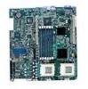
Server Board Connector and Component Locations The SCB2 comes in both SCSI and ATA versions. Figure 1 is a composite view of both versions. A BC D E F GH I J GG FF K EE DD CC BB L AA Z Y X W US Q OM VT RP N A. Speaker R. CPU 1 fan connector OM11707 B. ID LED S. Sys fan 1 connector C. Battery T. Aux fan connector D. Diagnostic LEDs (POST code) U. Floppy drive connector E. 66 MHz/64-bit PCI riser slot (full height) V. Fan module connector F. DIMM slots W. Main power connector G. I/O ports X. Auxiliary signal connector H. ICMB connector Y. Floppy/FP/IDE connector I. COM 1 serial header Z. Alternate front panel connector J. Chassis intrusion connector AA. ATA/IDE connector K. 66 MHz/64-bit PCI riser slot (low profile) BB. IPMB connector L. USB 3 & 4 header CC. SSI front panel connector M. Sys fan 3 connector DD. Configuration jumper block N. CPU 2 fan connector EE. ATA-100 connectors (ATA version only) O. Secondary processor socket FF. SCSI connector (SCSI version only) P. Primary processor socket GG. Hard Disk Drive LED header Q. Sys fan 2 connector Figure 1. Server Board Connector and Component Locations 8 Intel Server Board SCB2 Product Guide
-
 1
1 -
2
-
 3
3 -
 4
4 -
 5
5 -
 6
6 -
 7
7 -
 8
8 -
 9
9 -
 10
10 -
 11
11 -
 12
12 -
 13
13 -
14
-
15
-
16
-
17
-
18
-
19
-
20
-
21
-
22
-
23
-
24
-
25
-
26
-
27
-
28
-
29
-
30
-
31
-
32
-
33
-
34
-
35
-
36
-
37
-
38
-
39
-
40
-
41
-
42
-
43
-
44
-
45
-
46
-
47
-
48
-
49
-
50
-
51
-
52
-
53
-
54
-
55
-
56
-
57
-
58
-
59
-
60
-
61
-
62
-
63
-
64
-
65
-
66
-
67
-
68
-
69
-
70
-
71
-
72
-
73
-
74
-
75
-
76
-
77
-
78
-
79
-
80
-
81
-
82
-
83
-
84
-
85
-
86
-
87
-
88
-
89
-
90
-
91
-
92
-
93
-
94
-
95
-
96
-
97
-
98
-
99
-
100
-
101
-
102
-
103
-
104
-
105
-
106
-
107
-
108
 |
 |
