Intel SE7210TP1-E User Guide - Page 13
Server Board Connector and Component Locations, Server Board Features
 |
UPC - 810884006803
View all Intel SE7210TP1-E manuals
Add to My Manuals
Save this manual to your list of manuals |
Page 13 highlights
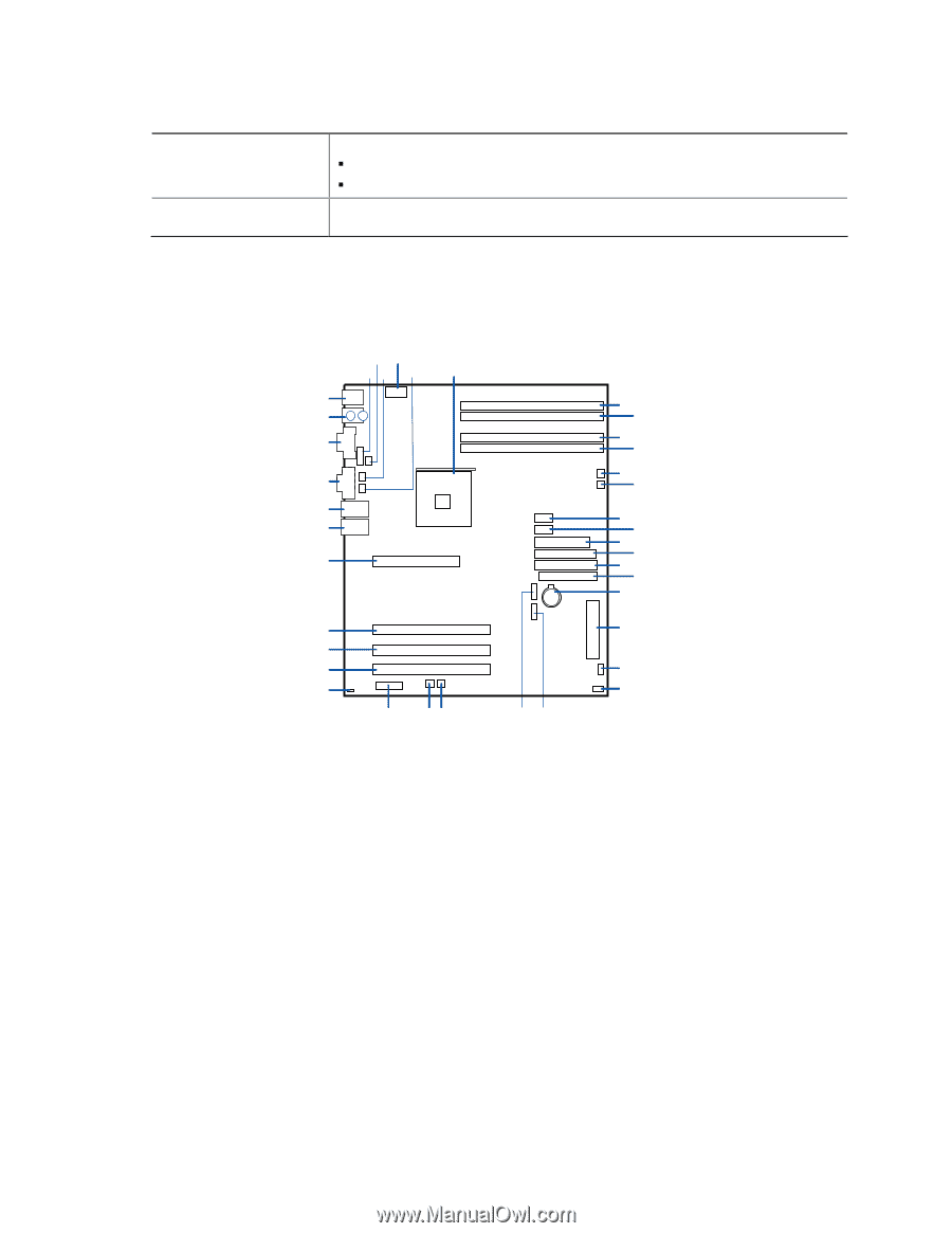
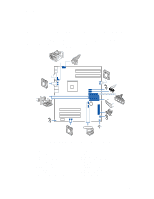
Server Board Features Server Board Features (continued) Power Management Support for ACPI: ƒ Suspend to RAM (STR) ƒ Wake on USB, PCI, RS-232, PS/2, LAN, and front panel Server Management Intel® Server Management 5.8 support via mini Baseboard Management Controller (mBMC) Server Board Connector and Component Locations BD AC E F ILIL HKHK GJJG FIIF EHEH DGDG CFFC EE DD CC BB AA Z Y A: Serial B Header B: CPU Fan Header C: Sys Fan Header 3 D: +12 V CPU Power Connector E: Sys Fan Header 4 F: Processor Socket G: DIMM 2B Socket H: DIMM 2A Socket I: DIMM 1B Socket J: DIMM 1A Socket K: Sys Fan Header 1 L: Sys Fan Header 2 M: Front Panel USB Header N: Aux Power Connector O: Main Power Connector P: Secondary IDE Connector Q: Primary IDE Connector R: Floppy Connector S: Battery M K G H I J K L M N O P Q R S T XW U V TP00507 T: Front Panel Connector U: Hot Swap Backplane Header V: SCSI LED Header W: SATA-A1 Connector X: SATA-A2 Connector Y: Sys Fan Header 6 Z: Sys Fan Header 5 AA: Jumper Block BB: Chassis Intrusion Header CC: PCI-X Slot 1, 64/66 RAIDIOS DD: PCI-X Slot 2, 64/66 EE: PCI-X Slot 3, 64/66 FF: PCI Slot 6, 32/33 GG: NIC 2 (10/100 Mbit) HH: NIC 1 (1 Gbit) II: Video Connector JJ: Serial A Connector KK: Keyboard and Mouse LL: USB Connectors Figure 2. Intel Server Board SE7210TP1-E Layout Intel Server Board SE7210TP1-E User Guide 13
-
 1
1 -
2
-
3
-
4
-
5
-
6
-
7
-
 8
8 -
 9
9 -
 10
10 -
 11
11 -
 12
12 -
 13
13 -
 14
14 -
 15
15 -
 16
16 -
 17
17 -
 18
18 -
19
-
20
-
21
-
22
-
23
-
24
-
25
-
26
-
27
-
28
-
29
-
30
-
31
-
32
-
33
-
34
-
35
-
36
-
37
-
38
-
39
-
40
-
41
-
42
-
43
-
44
-
45
-
46
-
47
-
48
-
49
-
50
-
51
 |
 |