Intel SE7210TP1-E User Guide - Page 9
s, Tables, Attaching the Fan Heat Sink Clips to the Processor Socket - memory
 |
UPC - 810884006803
View all Intel SE7210TP1-E manuals
Add to My Manuals
Save this manual to your list of manuals |
Page 9 highlights
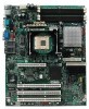
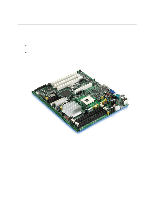
Contents Figures Figure 1. Intel® Server Board SE7210TP1-E 11 Figure 2. Intel Server Board SE7210TP1-E Layout 13 Figure 3. Making Connections to the Server Board 14 Figure 4. Configuration Jumper Location 15 Figure 5. Back Panel Connectors 16 Figure 6. Installing Memory 20 Figure 7. Installing the Processor in the Processor Socket 21 Figure 8. Attaching the Heat Sink to the Processor 22 Figure 9. Attaching the Fan Heat Sink Clips to the Processor Socket 22 Figure 10. Attaching the Fan Heat Sink Clips to the Processor Socket 23 Figure 11. Connecting the Processor Fan Cable to the Processor Fan Connector 23 Figure 12. Replacing the Battery 25 Tables Table 1. Table 2. Table 3. Table 4. Table 5. Table 6. Table 7. Table 8. Server Board Features 12 Configuration Jumper [J1D1 15 NIC LEDs...16 Keyboard Commands 27 BIOS Error Messages 41 Beep Codes 42 BIOS Recovery Beep Codes 42 Product Certification Markings 45 ix
-
 1
1 -
2
-
3
-
 4
4 -
 5
5 -
 6
6 -
 7
7 -
 8
8 -
 9
9 -
 10
10 -
 11
11 -
 12
12 -
 13
13 -
 14
14 -
15
-
16
-
17
-
18
-
19
-
20
-
21
-
22
-
23
-
24
-
25
-
26
-
27
-
28
-
29
-
30
-
31
-
32
-
33
-
34
-
35
-
36
-
37
-
38
-
39
-
40
-
41
-
42
-
43
-
44
-
45
-
46
-
47
-
48
-
49
-
50
-
51
 |
 |