JVC DR MV79B Instructions - Page 193
TV connection with RF Converter Modulator
 |
UPC - 046838034138
View all JVC DR MV79B manuals
Add to My Manuals
Save this manual to your list of manuals |
Page 193 highlights
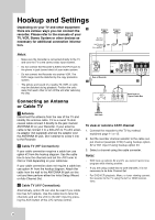
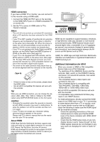
HOOKUP AND SETTINGS Connections to your TV • Make one of the following connections, depending on the capabilities of your TV. • One of these connections must be made (or HDMI) in order to view DVD/VHS playback, Tuner, or On Screen Menu functions." RF coaxial connection Connect the ANTENNA OUT jack on the Recorder to the antenna in jack on the TV using the supplied 75ohm Coaxial Cable (R). This connection will only include the same signal as the Antenna In jack. DVD/VHS playback or Tuner output is not possible from this connection. Please see Video connection, S-Video connection, Component Video connection, or HDMI connection sections. Also see the Audio connection section. Audio connection Connect the Left and Right AUDIO OUTPUT jacks on the Recorder to the audio left/right in jacks on the TV using the supplied audio cables (A1 or A2). Rear of TV S-VIDEO INPUT COMPONENT/PROGRESSIVE SCAN VIDEO INPUT AUDIO INPUT Pr Pb Y R L S C A2 Rear of Recorder Video connection Connect the VIDEO OUTPUT jack on the Recorder to the video in jack on the TV using the video cable supplied (V). Note: If you use this connection, set the TV's source selector to VIDEO. You must make this connection to view DVD or VCR playback, and to watch channels being recorded from the built in Tuner. S-Video connection Connect the S-VIDEO OUTPUT jack on the Recorder to the S-Video in jack on the TV using the optional S-Video cable (S). Component Video connection If your television is a high-definition or "digital ready" television, you may take advantage of the Recorder's progressive scan output for the highest video resolution possible. Connect the COMPONENT OUTPUT jacks on the Recorder to the corresponding in jacks on the TV using an optional Y PB PR cable (C). Notes: • Set the resolution to 480p using OUTPUT STATUS button on the front panel for progressive signal. • Progressive Scan does not work with the RF, Video or S-Video connections. • If your TV does not accept the Progressive Scan format, the picture will appear scrambled. R V A1 Rear of TV TV connection with RF Converter (Modulator) If your TV does not have A/V Input jack but only Antenna Input jack, you must use the RF Converter as below. Rear of Recorder AV INPUT RF Modulator (Not Supplied) Rear of TV 11
-
 1
1 -
2
-
3
-
4
-
5
-
6
-
7
-
8
-
9
-
10
-
11
-
12
-
13
-
14
-
15
-
16
-
17
-
18
-
19
-
20
-
21
-
22
-
23
-
24
-
25
-
26
-
27
-
28
-
29
-
30
-
31
-
32
-
33
-
34
-
35
-
36
-
37
-
38
-
39
-
40
-
41
-
42
-
43
-
44
-
45
-
46
-
47
-
48
-
49
-
50
-
51
-
52
-
53
-
54
-
55
-
56
-
57
-
58
-
59
-
60
-
61
-
62
-
63
-
64
-
65
-
66
-
67
-
68
-
69
-
70
-
71
-
72
-
73
-
74
-
75
-
76
-
77
-
78
-
79
-
80
-
81
-
82
-
83
-
84
-
85
-
86
-
87
-
88
-
89
-
90
-
91
-
92
-
93
-
94
-
95
-
96
-
97
-
98
-
99
-
100
-
101
-
102
-
103
-
104
-
105
-
106
-
107
-
108
-
109
-
110
-
111
-
112
-
113
-
114
-
115
-
116
-
117
-
118
-
119
-
120
-
121
-
122
-
123
-
124
-
125
-
126
-
127
-
128
-
129
-
130
-
131
-
132
-
133
-
134
-
135
-
136
-
137
-
138
-
139
-
140
-
141
-
142
-
143
-
144
-
145
-
146
-
147
-
148
-
149
-
150
-
151
-
152
-
153
-
154
-
155
-
156
-
157
-
158
-
159
-
160
-
161
-
162
-
163
-
164
-
165
-
166
-
167
-
168
-
169
-
170
-
171
-
172
-
173
-
174
-
175
-
176
-
177
-
178
-
179
-
180
-
181
-
182
-
183
-
184
-
185
-
186
-
187
-
 188
188 -
 189
189 -
 190
190 -
 191
191 -
 192
192 -
 193
193 -
 194
194 -
 195
195 -
 196
196 -
 197
197 -
 198
198 -
199
-
200
-
201
-
202
-
203
-
204
-
205
-
206
-
207
-
208
-
209
-
210
-
211
-
212
-
213
-
214
-
215
-
216
-
217
-
218
-
219
-
220
-
221
-
222
-
223
-
224
-
225
-
226
-
227
-
228
-
229
-
230
-
231
-
232
-
233
-
234
-
235
-
236
-
237
-
238
-
239
-
240
-
241
-
242
-
243
-
244
-
245
-
246
-
247
-
248
-
249
-
250
-
251
-
252
-
253
-
254
-
255
-
256
-
257
-
258
-
259
-
260
-
261
-
262
-
263
-
264
-
265
-
266
-
267
-
268
-
269
-
270
-
271
-
272
-
273
-
274
-
275
-
276
-
277
-
278
-
279
-
280
-
281
-
282
-
283
-
284
-
285
-
286
-
287
-
288
-
289
-
290
-
291
-
292
-
293
-
294
-
295
-
296
-
297
-
298
-
299
-
300
-
301
-
302
-
303
-
304
-
305
-
306
 |
 |
