JVC GM-F420S Instruction Manual - Page 6
Connections
 |
View all JVC GM-F420S manuals
Add to My Manuals
Save this manual to your list of manuals |
Page 6 highlights
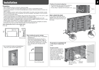
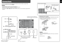
Connections Select the most appropriate terminal referring to the illustration below and the tables on page 7 when connecting equipment to the terminals A - J . CAUTION • Before making any connections, turn off all the equipment. • DO NOT connect the power cord until all connections are completed. • Refer also to the user manual of each piece of equipment. • Do not short-circuit 9 and ( speaker cords to each other. (Refer also to the instructions supplied with the speakers.) To bind the cables (example): 6 Insert the end of the cramp into the hole pointed with 3. Push the tab to detach the Cord cramp (supplied) cramp. A B VIDEO IN C DVI-D (HDCP) RGB IN RGB OUT F VIDEO OUT G AUDIO 1 IN D E AUDIO 2 IN AUDIO 1 OUT H AUDIO 2 OUT I RS-232C RS-485 IN/OUT LAN External control equipment For details, see page 20. An external unit can be installed here. Consult your dealer for more information. Attaching the power cord holder The provided power cord holder prevents accidental disconnection of the AC power cord from the AC IN terminal. • The power cord holder consists of two parts, a case and a cover. 1 AC IN terminal 2 Cover Case J SENSOR EXT. SPEAKER OUT AC OUT Power supply for an external unit (Max. 2A). Consult your dealer for more information. AC IN To wall outlet Motion sensor (see page 18) 3 CAUTION • Use only the provided screws. • Make sure the plug will not be pulled out after the cover is attached to the case. To detach the cover
-
 1
1 -
 2
2 -
 3
3 -
 4
4 -
 5
5 -
 6
6 -
 7
7 -
 8
8 -
 9
9 -
 10
10 -
 11
11 -
 12
12 -
13
-
14
-
15
-
16
-
17
-
18
-
19
-
20
-
21
-
22
-
23
-
24
-
25
-
26
-
27
-
28
-
29
-
30
-
31
-
32
 |
 |
