JVC TK-C553U Instruction Manual - Page 8
Controls, Connectors and Indicators
 |
View all JVC TK-C553U manuals
Add to My Manuals
Save this manual to your list of manuals |
Page 8 highlights
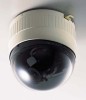
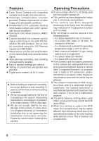
Controls, Connectors and Indicators Camera Body Ⅲ Body Surface View when the dome cover is removed. 1 MONITOR 2 LOCK LEFT AWC INT OFF TERMINATION UP RIGHT SET NOT USED NOT USED L/L ON DOWN 7 3 6 4 5 1 MONITOR terminal (RCA pin) For connecting a monitor when determining camera angle, etc. (High impedance) 2 Camera head 3 Horizontal LOCK screw When adjusting the camera angles horizontal rotation, this screw is loosened for adjustment and tightened to maintain the angle. 4 Camera clamp Fix the camera body to the ceiling mount by fastening the camera clamping screw of the ceiling mount to this clamp. 5 Operation buttons LEFT/RIGHT/UP/DOWN Used to move the cursor on the SETUP MENU screens and for changing set values. AWC Press for about 1 second to activate the one-push auto white balance. Even if the color temperature changes later on, the white balance does not adjust to the change. 6 SET button Press to display and close the setup screen. 8
-
 1
1 -
2
-
 3
3 -
 4
4 -
 5
5 -
 6
6 -
 7
7 -
 8
8 -
 9
9 -
 10
10 -
 11
11 -
 12
12 -
 13
13 -
14
-
15
-
16
-
17
-
18
-
19
-
20
-
21
-
22
-
23
-
24
-
25
-
26
-
27
-
28
-
29
-
30
-
31
-
32
-
33
-
34
-
35
-
36
-
37
-
38
-
39
-
40
-
41
-
42
-
43
-
44
 |
 |
