Jensen MCD9424RC Operation Manual - Page 13
Wiring Diagram - wiring harness
 |
UPC - 043258014030
View all Jensen MCD9424RC manuals
Add to My Manuals
Save this manual to your list of manuals |
Page 13 highlights
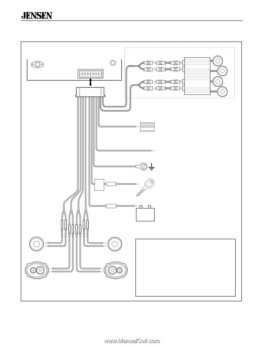
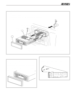
® Wiring Diagram Antenna Jack Remote Plug MCD 9424JA RCA-to-RCA cables (not supplied) Red (RF) Amplifier wiring (See amplifier instructions) White (LF) Red (RR) AMP White (LR) Note: If a Dimmer Wire or Illumination Circuit cannot be found then connect the "Dark Blue Remote Lead" and the "Orange Dimmer" wire together. LF LF- white/black white LF+ LR- green/black green LR+ LR Dark Blue Amp AMP Connect to the amplifier. If not used, tape bare end of wire. Orange Dimmer Connect to existing dimmer wire. Black Filter Box In-line Fuse (10-amp) Red Ground Connect to ground terminal. Accessory Connect to existing radio wire or radio fuse. In-line Yellow Fuse (0.5-amp) RF- RF gray/black gray RF+ RR- violet/black violet RR+ RR +- Memory Connect to battery or 12 volt power source that is always live. The radio will not work if this wire is not connected. Fuses When replacing a fuse, make sure new fuse is correct type and amperage. Using an incorrect fuse could damage radio. The MCD 9424JA uses two fuses with in-line fuse holders as part of rear wiring harness: • 10 amp fast blow AGC (red wire). • 0.5 amp fast blow AGC (yellow wire). Go to "Testing" on page 5. 4
-
 1
1 -
2
-
3
-
4
-
5
-
6
-
7
-
 8
8 -
 9
9 -
 10
10 -
 11
11 -
 12
12 -
 13
13 -
 14
14 -
 15
15 -
 16
16 -
 17
17 -
 18
18
 |
 |