LG 26LX2R Owners Manual - Page 52
External, Control, Device, Setup - rt
 |
View all LG 26LX2R manuals
Add to My Manuals
Save this manual to your list of manuals |
Page 52 highlights
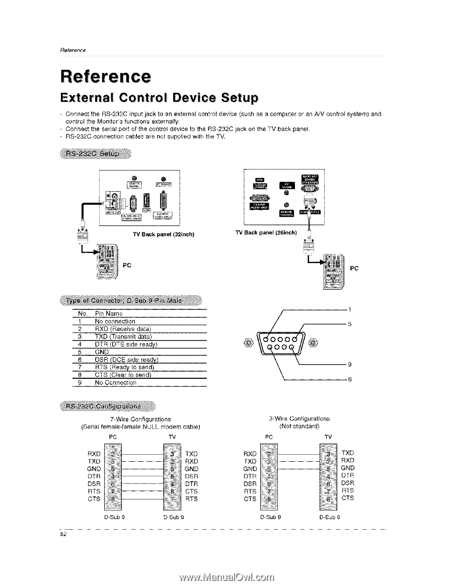
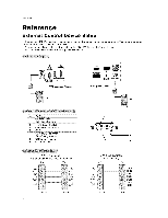
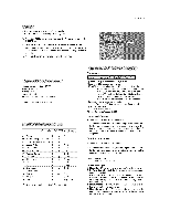
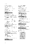
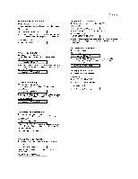
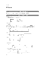
Reference External Control Device Setup - Connect the RSo232C input jack to an external control device (such as a computer or an A!V control system) and control the Monitor's functions externally. - Connect the serial port of the control device to the RS°232C jack on the TV back panel, - RS_232C connection cables are not supplied with the TV, O O PC m Q o m TV Back panel (26inch) PC 1 No. Pin Name 1 No connection 5 2 RXD (Receive data) 3 TXD (Transmit data) 4 DTR (DTE side ready) 5 GND 6 DSR (DCE side ready) !Readt:o,end) 9 8 CTS (CUear to send) 9 No Connection 6 7-Wire Configurations (Serial female-female NULL modem cable) PC TV 3-Wire Configurations (Not standard) PC TV RXD TXD GND DTR DSR RTS CTS iiiiiii!iii!:!i_!_!_!ii!ii!i!ii!iii_ii_iiii!!ii!i!_i!!i!i!!i!iiiTi_Xi!D RXD !i!i!i!i!i!i!iii,R:iiX_Di!21!i!i!i!_i!i!i!_!iiii TXD i!i!i!i!i!i!i!i!Gi!iNi_D511!i!ii!ii!ii!ii!iii:!i! GND iiiilili!i!iii!ii!Dii!SiiiR!i61iiiiiiiiiiiiiiiiiiiii DTR DTR DSR C...T..S RTS RTS CTS T:::X::D RXD GND DT R DSR ..... RTS iiii!iiiii!iiiii!i!i!i!!_!8!i!i!i!i!i!iiiji!_ CTS D-Sub 9 D_Sub D-Sub 9 D-Sub 52
-
 1
1 -
2
-
3
-
4
-
5
-
6
-
7
-
8
-
9
-
10
-
11
-
12
-
13
-
14
-
15
-
16
-
17
-
18
-
19
-
20
-
21
-
22
-
23
-
24
-
25
-
26
-
27
-
28
-
29
-
30
-
31
-
32
-
33
-
34
-
35
-
36
-
37
-
38
-
39
-
40
-
41
-
42
-
43
-
44
-
45
-
46
-
 47
47 -
 48
48 -
 49
49 -
 50
50 -
 51
51 -
 52
52 -
 53
53 -
 54
54 -
 55
55 -
 56
56 -
 57
57 -
58
-
59
-
60
-
61
-
62
-
63
-
64
 |
 |