LG DLG2532W Owners Manual - Page 13
Electrical, Connection, Options, if your home has: And you will, Go to connecting, wire - remove panel
 |
View all LG DLG2532W manuals
Add to My Manuals
Save this manual to your list of manuals |
Page 13 highlights
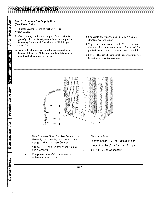
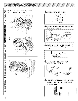
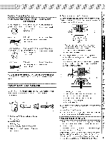
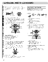
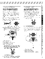
Electrical Connection Options if your home has: And you will _ connecting to Go to Section 4-wire receptacle A UL listed, 120/240 4-wire connection: (NEMATypei4°30R) volt minimum, 30 amp, dryer power supply cord* Power supply cord 4-wire direct x_ A fused 4-wire connection: disconnect or circuit Direct Wire breaker box* 3-wire receptacle (N EMAty pe 10-30 R) A UL listed, i20/240 volt minimum 30 amp, dryer power supply cord* 3owire connection: Power supply cord 3-wire direct "_ A fused 3owire connection: disconnect or circuit Direct Wire breaker box* if local c_es do not permit the connection of a frame,rounding conductor to the neutral wire, go to "Optional 3°wire connection" section. 4-wire connection: Power supply cord IMPORTANT: A 4-wire connection is required for mobile homes and where local codes d_ not permit the use of 3 wire con nections, 34 1.4-wire receptacle (NEMA type 14-30R) 2, 4-prong plug 3, Ground prong 4, Neutral prong 5, Spade terminals with upturned ends 6. 3/4 in. (1.9 cm) UL approved strain relief 7, Ring terminals 1, Remove center terminal block screw, 2. Remove appliance ground wire (green) from extemai ground connector screw, Fasten it under center, silver colored terminal block screw. 1. External ground connector - Dotted line shows position of NEUTRAL ground wire before _ing moved to center terminal block _rew_- 2. Center silver-colored terminal block screw 3. Green wire of harness 3, Connect ground wire (green or bare) of power supply cable to external ground conductor screw. Tighten screw, 4. Conn_t neutral wire (white or center wire) of power supply cord to the center, silver colored terminal screw of the terminal block. 4 I5 --6 1. External ground connector 2. Green or bare copper wire of power supply cord 3. 3/4 in, (1,9 cm) UL-tisted strain relief 4. Center silver-colored terminal block screw 5. Neutral grounding wire (green) 6. Neutral wire (white) 5, Connect the other wires to outer terminal block screws Tighten screws. 6, Tighten strain relief screws, 7. Insert t_ of terminal block cover into slot of dryer rear panel Secure cover with hold-down screw 4-wire connection: Direct wire IMPORTANT: A 4-wire connection is r_uired for mobile homes and where local codes do not permit the use of 3 wire connections. Direct wire cable must have 5 ft (i ,52 m) of extra length so dryer can be moved if needed. Strip 5 in, (12,7 cm) of outer covering from end of cable, leaving bare ground wire at 5 in. (12.7 cm). Cut Vi2 in. (3,8 cm) from 3 remaining wires, Strip insulation back i in. (2.5 cm). Shape ends of wires into a h_k shape. 13
-
 1
1 -
2
-
3
-
4
-
5
-
6
-
7
-
 8
8 -
 9
9 -
 10
10 -
 11
11 -
 12
12 -
 13
13 -
 14
14 -
 15
15 -
 16
16 -
 17
17 -
 18
18 -
19
-
20
-
21
-
22
-
23
-
24
-
25
-
26
-
27
-
28
-
29
-
30
-
31
-
32
 |
 |
