Lantronix MatchPort b/g MatchPort b/g - Integration Guide - Page 10
Serial Input/Output, MatchPort b/g, DCE Connector, MatchPort, b/g Signal, logic, Description, RS485
 |
View all Lantronix MatchPort b/g manuals
Add to My Manuals
Save this manual to your list of manuals |
Page 10 highlights
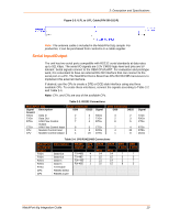
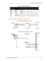
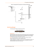
2: Description and Specifications Figure 2-3. U.FL to U.FL Cable (P/N 500-181-R) Note: The antenna cable is included in the MatchPort b/g sample. For production, it can be purchased from Lantronix or a cable supplier. Serial Input/Output The unit has two serial ports compatible with RS232 serial standards at data rates up to 921 Kbps. The serial I/O signals are 3.3V CMOS logic level and pins are 5V tolerant. Serial signals connect to the OEM CPU/UART. For evaluation and prototype work, it is convenient to have an external RS-232 interface that can connect to the serial port on a PC. The MatchPort Demo Board has RS-232/422/485 transceivers to implement this external interface. If desired, use the CPs to create a DTE or DCE-style interface using any three available CPs. To create these interfaces, connect the signals according to Table 2-2 and Table 2-4. Note: CPx, and CPy are any of the available CPs. Table 2-2. RS232 Connections MatchPort b/g Signal Description (Logic) RXDx Data In TXDx Data Out RTSx H/W Flow Control Output CTSx H/W Flow Control Input CPx Modem Control Input CPy Modem Control Output DCE Connector DB9 DB25 2 3 3 2 7 4 8 5 1 8 4 20 Signal RXDx TXDx RTSx CTSx DCDx DTRx DTE Connector DB9 DB25 3 2 2 3 8 5 7 4 4 20 1 8 Signal TXDx RXDx CTSx RTSx DTRx DCDx Table 2-4. JP6 RS422/485 Connections MatchPort b/g Signal (logic) TXD1 TXD1 RXD1 RXD1 RTS1 CP3 CP4 Description Data Out Data Out Data In Data In TX Enable RS485 Select RS485 2-wire RS485 JP6 DB25 DB25 Signal Pin 4 2 Wire Wire TX+485 4 14 14 TX-485 3 15 15 RX+485 2 21 14 RX-485 1 22 15 DB9 DB9 4 wire 2 wire 7 7 3 3 2 7 8 3 MatchPort b/g Integration Guide 10
-
 1
1 -
2
-
3
-
4
-
 5
5 -
 6
6 -
 7
7 -
 8
8 -
 9
9 -
 10
10 -
 11
11 -
 12
12 -
 13
13 -
 14
14 -
 15
15 -
16
-
17
-
18
-
19
-
20
-
21
-
22
-
23
-
24
-
25
-
26
-
27
-
28
-
29
 |
 |
