Lantronix MatchPort b/g MatchPort b/g - Integration Guide - Page 20
: Demonstration Kit, Contents of the Kit, Demo Board Description, Serial Interfaces
 |
View all Lantronix MatchPort b/g manuals
Add to My Manuals
Save this manual to your list of manuals |
Page 20 highlights
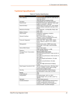
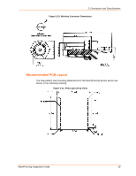
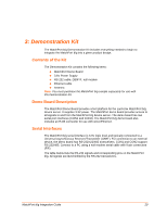
3: Demonstration Kit The MatchPort b/g Demonstration Kit includes everything needed to begin to integrate the MatchPort b/g into a given product design. Contents of the Kit The Demonstration Kit contains the following items: MatchPort Demo Board 3.6V Power Supply RS-232 cable, DB9F/F, null modem Ethernet cable Antenna Note: You must purchase the MatchPort b/g sample separately for use with this Demonstration Kit. Demo Board Description The MatchPort Demo Board provides a test platform for the Lantronix MatchPort b/g device server. It supplies 3.3V power. The MatchPort demo board provides access to all signals to and from the MatchPort b/g device server. The demo board has two serial port interfaces (CON1 and CON2). The MatchPort b/g demo board also includes an RJ45 connector for use with wired Ethernet. Serial Interfaces The MatchPort b/g serial interface is 3.3V logic level and typically connected to a Universal Asynchronous Receiver/Transmitter (UART). For connection to an external device, the demo board has RS-232/422/485 transceivers. CON1 and CON2 support RS-232/485. Connect to a PC using a null-modem serial cable with 9-pin connectors (F/F). The table below lists the RS-232 signals and corresponding pins on the MatchPort b/g. All signals are level-shifted by the RS-232 transceivers. MatchPort b/g Integration Guide 20
-
 1
1 -
2
-
3
-
4
-
5
-
6
-
7
-
8
-
9
-
10
-
11
-
12
-
13
-
14
-
 15
15 -
 16
16 -
 17
17 -
 18
18 -
 19
19 -
 20
20 -
 21
21 -
 22
22 -
 23
23 -
 24
24 -
 25
25 -
26
-
27
-
28
-
29
 |
 |
