Lantronix MatchPort b/g MatchPort b/g - Integration Guide - Page 18
Recommended PCB Layout, Wireless Connector Dimensions, PCB Layout Top View
 |
View all Lantronix MatchPort b/g manuals
Add to My Manuals
Save this manual to your list of manuals |
Page 18 highlights
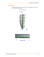
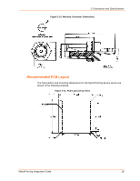
2: Description and Specifications Figure 2-10. Wireless Connector Dimensions Recommended PCB Layout The hole pattern and mounting dimensions for the MatchPort b/g device server are shown in the following drawing: Figure 2-11. PCB Layout (Top View) MatchPort b/g Integration Guide 18
-
 1
1 -
2
-
3
-
4
-
5
-
6
-
7
-
8
-
9
-
10
-
11
-
12
-
 13
13 -
 14
14 -
 15
15 -
 16
16 -
 17
17 -
 18
18 -
 19
19 -
 20
20 -
 21
21 -
 22
22 -
 23
23 -
24
-
25
-
26
-
27
-
28
-
29
 |
 |

2: Description and Specifications
MatchPort b/g Integration Guide
18
Figure 2-10. Wireless Connector Dimensions
Recommended PCB Layout
The hole pattern and mounting dimensions for the MatchPort b/g device server are
shown in the following drawing:
Figure 2-11. PCB Layout (Top View)