Lantronix MatchPort b/g MatchPort b/g - Integration Guide - Page 21
Power Supply, General Control, Configuration Switch Bank, MatchPort b/g, PIN FUNCTION, MatchPort
 |
View all Lantronix MatchPort b/g manuals
Add to My Manuals
Save this manual to your list of manuals |
Page 21 highlights
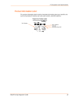
3:Demonstration Kit Table 3-1. RS-232 Signals MatchPort b/g PIN FUNCTION UART x TXDx (Data Out) RXDx (Data In) CTSx (HW Flow Control Input) RTSx (HW Flow Control Output) DCDx (Modem Control Input) DTRx (Modem Control Output) DB9 Pin # Conx 3 2 8 7 1 4 Table 3-2. RS-485 4-Wire Connector MatchPort b/g Signal TX+ TXRX+ RX- Description Data Out Data Out Data In Data In DB9 Pin # 7 3 2 8 Power Supply The demo board uses an external 3.3V regulated supply (included with kit). The demo board contains additional filtering and protection. General Control The following table denotes the configuration of the demo board. Configuring the jumper re-routes the signals on the demo board as required for a given product. This also drives the LEDs. Configuration Switch Bank JP1 pin/Signal 1/CP1 3/CP2 5/CP3 7/CP4 9/CP5 11/CP6 13/CP7 15/CP8 Table 3-3. Demo Board JP1 Jumper Configuration JP1 pin/Signal 2/LED12 4/LED11 6/LED10 8/LED9 10/LED8 12/LED7 14/LED6 16/LED5 Function Jumper 1-2, CP1Controls LED12 Jumper 3-4, CP2 Controls LED11 Jumper 5-6, CP3 Controls LED10 Jumper 7-8, CP4 Controls LED9 Jumper 9-10, CP5 Controls LED8 Jumper 11-12, CP6 controls LED7 Jumper 13-14, CP7 controls LED6 Jumper 15-16, CP8 controls LED5 MatchPort b/g Integration Guide 21
-
 1
1 -
2
-
3
-
4
-
5
-
6
-
7
-
8
-
9
-
10
-
11
-
12
-
13
-
14
-
15
-
 16
16 -
 17
17 -
 18
18 -
 19
19 -
 20
20 -
 21
21 -
 22
22 -
 23
23 -
 24
24 -
 25
25 -
 26
26 -
27
-
28
-
29
 |
 |
