Lantronix MatchPort b/g MatchPort b/g - Integration Guide - Page 11
Sample Layouts for RS-485 Connectivity, MatchPort, b/g Signal, logic, Description, RS-485, Signal
 |
View all Lantronix MatchPort b/g manuals
Add to My Manuals
Save this manual to your list of manuals |
Page 11 highlights
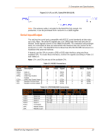
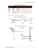
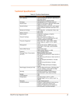
2: Description and Specifications Table 2-3. JP9 RS-422/485 Connections MatchPort b/g Signal (logic) TXD2 TXD2 RXD2 RXD2 RTS2 CP7 CP8 Description Data Out Data Out Data In Data In TX Enable RS-485 Select RS-485 2-wire RS-485 JP9 DB25 DB25 Signal Pin 4 2 Wire Wire TX+485 4 14 14 TX-485 3 15 15 RX+485 2 21 14 RX-485 1 22 15 DB9 DB9 4 wire 2 wire 7 7 3 3 2 7 8 3 Sample Layouts for RS-485 Connectivity Figure 2-4. Combined RS-232/422 Transceiver Figure 2-5. Separate RS-232/422 Transceivers MatchPort b/g Integration Guide 11
-
 1
1 -
2
-
3
-
4
-
5
-
 6
6 -
 7
7 -
 8
8 -
 9
9 -
 10
10 -
 11
11 -
 12
12 -
 13
13 -
 14
14 -
 15
15 -
 16
16 -
17
-
18
-
19
-
20
-
21
-
22
-
23
-
24
-
25
-
26
-
27
-
28
-
29
 |
 |

2: Description and Specifications
MatchPort b/g Integration Guide
11
Table 2-3. JP9 RS-422/485 Connections
MatchPort
b/g Signal
(logic)
Description
RS-485
Signal
JP9
Pin
DB25
4
Wire
DB25
2
Wire
DB9
4 wire
DB9
2 wire
TXD2
Data Out
TX+485
4
14
14
7
7
TXD2
Data Out
TX-485
3
15
15
3
3
RXD2
Data In
RX+485
2
21
14
2
7
RXD2
Data In
RX-485
1
22
15
8
3
RTS2
TX Enable
CP7
RS-485 Select
CP8
RS-485 2-wire
Sample Layouts for RS-485 Connectivity
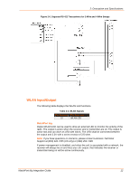
Figure 2-4. Combined RS-232/422 Transceiver
Figure 2-5. Separate RS-232/422 Transceivers