Lantronix MatchPort b/g MatchPort - DemoKit Quick Start Guide - Page 4
Introduction, Demonstration Kit Contents, What You Need to Know, Hardware Address, IP Address
 |
View all Lantronix MatchPort b/g manuals
Add to My Manuals
Save this manual to your list of manuals |
Page 4 highlights
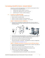
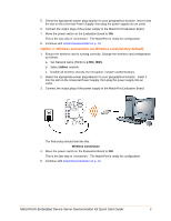
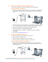
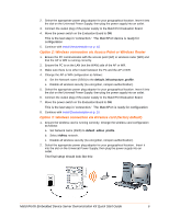
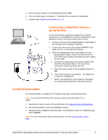
Introduction Thank you for purchasing the Lantronix® MatchPort® Embedded Device Server Demonstration Kit. This quick start guide describes the procedures for initial connection to the MatchPort device through either a network connection or serial port. Once a connection is established you can use the WebManager or command line interface (CLI) for configuration and control. Demonstration Kit Contents Ethernet cable 10 ft MatchPort Evaluation Board Antenna - 2.4 GHz 2.15 dbi reverse polarity SMA. 3.3V-wall-mount power supply AC/DC, 1A RS-232, DB9F/F, 10 ft, null modem cable SMA to UFL adapter cable Note: The MatchPort device must be purchased separately. For the latest revision of this product document, please check our online documentation at www.lantronix.com/support/documentation. What You Need to Know Hardware Address You need to know the unit hardware address (also known as MAC address) to identify the unit in the DeviceInstaller™ search list. It is on the product label in the format: 00-20-4a-XX-XX-XX, where the XXs are unique numbers assigned to the product. Hardware Address: 00-20-4a IP Address Your MatchPort device will need a unique IP address on your network. By default, the MatchPort device is assigned an IP address by your DHCP server. If no DHCP server is available, the MatchPort will generate an AutoIP address (169.254.xxx.xxx). If you are planning to use a static IP address, make note of it. The system administrator generally provides the IP address, subnet mask, and gateway. The IP address must be within a valid range, unique to your network, and in the same subnet as your PC. IP Address Subnet Mask Gateway MatchPort® Embedded Device Server Demonstration Kit Quick Start Guide 4
-
 1
1 -
 2
2 -
 3
3 -
 4
4 -
 5
5 -
 6
6 -
 7
7 -
 8
8 -
 9
9 -
 10
10 -
11
-
12
 |
 |
