Lantronix UDS-10 UDS-10 / UDS100 - User Guide - Page 53
Null-Modem Cable, Network Port, UDS10/UDS100 User Guide, Connectons and Pinouts
 |
View all Lantronix UDS-10 manuals
Add to My Manuals
Save this manual to your list of manuals |
Page 53 highlights
UDS10/UDS100 User Guide Connectons and Pinouts Null-Modem Cable When attaching the DB9 of the UDS to the DB9 com port on a PC, use a null-modem cable (Lantronix Part No. 500-163). The figure below shows the pinouts for a DB9 to DB9 null-modem cable. To configure the UDS using the DB9 serial port, you only need to pinout the TXD, RXD, and GND signals. Figure 9-4. Null-Modem Cable (Lantronix Part No. 500-163) Network Port The unit's back panel contains a power plug and an RJ45 (10/100) Ethernet port. Power input range on the power plug is 9-30 VDC or 9-24 VAC. Figure 9-5. Network Interface 53
-
 1
1 -
2
-
3
-
4
-
5
-
6
-
7
-
8
-
9
-
10
-
11
-
12
-
13
-
14
-
15
-
16
-
17
-
18
-
19
-
20
-
21
-
22
-
23
-
24
-
25
-
26
-
27
-
28
-
29
-
30
-
31
-
32
-
33
-
34
-
35
-
36
-
37
-
38
-
39
-
40
-
41
-
42
-
43
-
44
-
45
-
46
-
47
-
 48
48 -
 49
49 -
 50
50 -
 51
51 -
 52
52 -
 53
53 -
 54
54 -
 55
55 -
 56
56 -
 57
57 -
 58
58 -
59
-
60
-
61
-
62
-
63
-
64
-
65
-
66
-
67
-
68
-
69
-
70
-
71
-
72
-
73
-
74
-
75
-
76
-
77
-
78
 |
 |
UDS10/UDS100 User Guide
Connectons and Pinouts
53
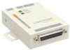
Null-Modem Cable
When attaching the DB9 of the UDS to the DB9 com port on a PC, use a null-modem
cable (Lantronix Part No. 500-163). The figure below shows the pinouts for a DB9 to
DB9 null-modem cable. To configure the UDS using the DB9 serial port, you only
need to pinout the TXD, RXD, and GND signals.
Figure 9-4. Null-Modem Cable (Lantronix Part No. 500-163)
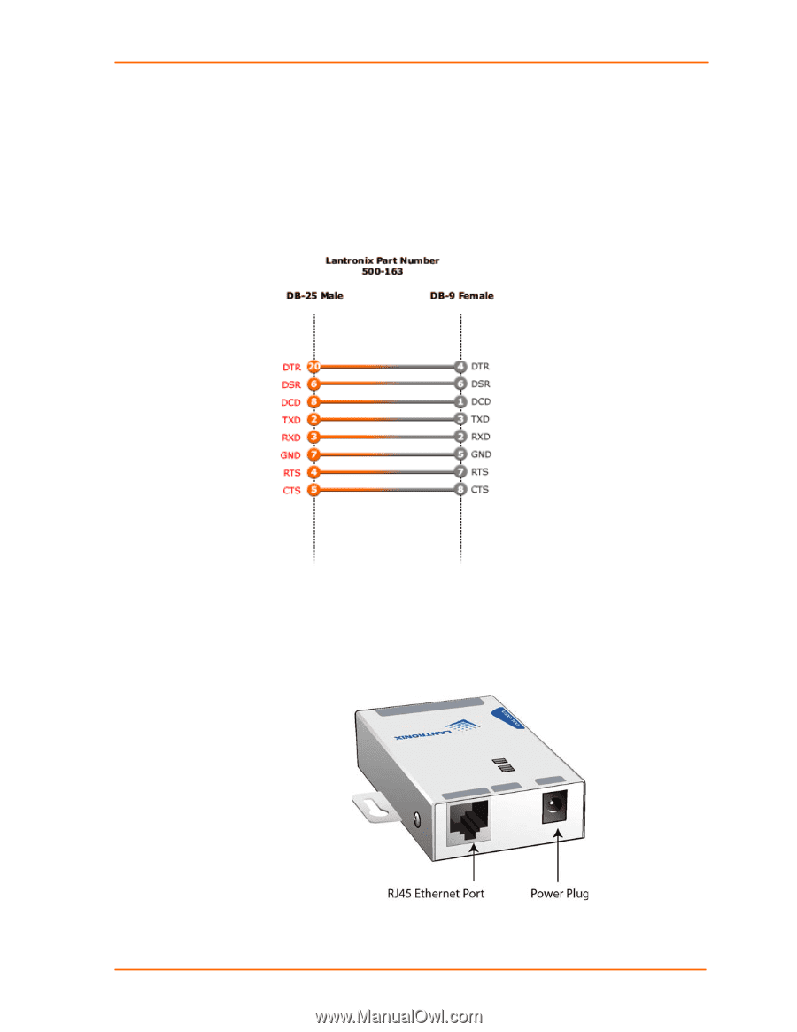
Network Port
The unit's back panel contains a power plug and an RJ45 (10/100) Ethernet port.
Power input range on the power plug is 9-30 VDC or 9-24 VAC.
Figure 9-5. Network Interface