Lenovo 63 Lenovo 63 Hardware Maintenance Manual - Page 70
Locating connectors on the rear of your computer, Locating major FRUs and CRUs
 |
View all Lenovo 63 manuals
Add to My Manuals
Save this manual to your list of manuals |
Page 70 highlights
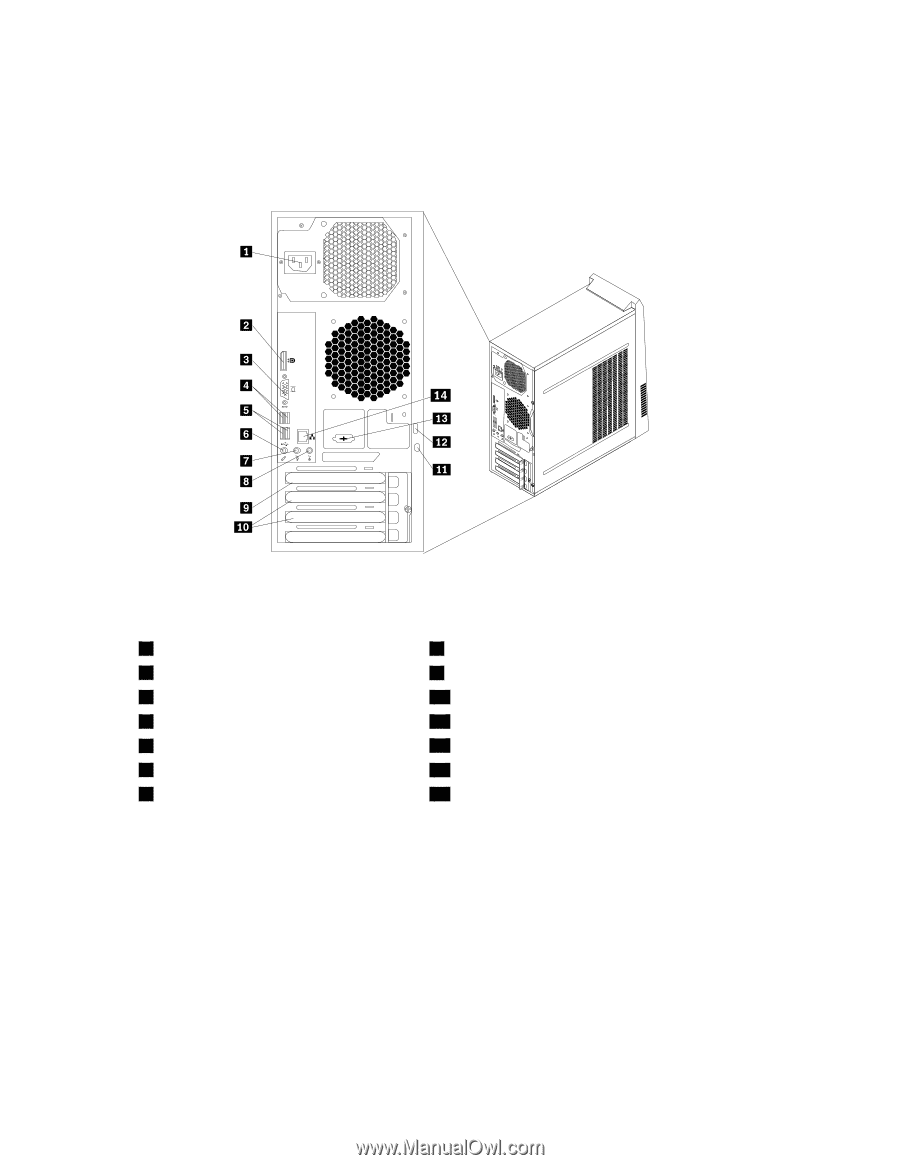
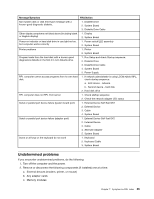
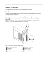
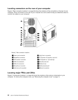
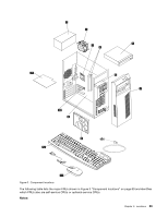
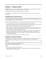
Locating connectors on the rear of your computer Figure 2 "Rear connector locations" on page 68 shows the locations of the connectors on the rear of your computer. Some connectors on the rear of your computer are color-coded to help you determine where to connect the cables on your computer. 56 34 34 Figure 2. Rear connector locations 1 Power cord connector 2 DisplayPort connector 3 VGA monitor connector 4 USB 3.0 connectors 5 USB 2.0 connectors 6 Microphone connector 7 Audio line-out connector 8 Audio line-in connector 9 PCI Express x16 graphics card slot 10 PCI Express x1 card slots (2) 11 Security-lock slot 12 Padlock loop 13 Optional serial port 14 Ethernet connector Locating major FRUs and CRUs Figure 3 "Component locations" on page 69 shows the locations of the various components in your computer. To remove the computer cover, see "Removing the computer cover" on page 74. 68 Lenovo Hardware Maintenance Manual
-
 1
1 -
2
-
3
-
4
-
5
-
6
-
7
-
8
-
9
-
10
-
11
-
12
-
13
-
14
-
15
-
16
-
17
-
18
-
19
-
20
-
21
-
22
-
23
-
24
-
25
-
26
-
27
-
28
-
29
-
30
-
31
-
32
-
33
-
34
-
35
-
36
-
37
-
38
-
39
-
40
-
41
-
42
-
43
-
44
-
45
-
46
-
47
-
48
-
49
-
50
-
51
-
52
-
53
-
54
-
55
-
56
-
57
-
58
-
59
-
60
-
61
-
62
-
63
-
64
-
 65
65 -
 66
66 -
 67
67 -
 68
68 -
 69
69 -
 70
70 -
 71
71 -
 72
72 -
 73
73 -
 74
74 -
 75
75 -
76
-
77
-
78
-
79
-
80
-
81
-
82
-
83
-
84
-
85
-
86
-
87
-
88
-
89
-
90
-
91
-
92
-
93
-
94
-
95
-
96
-
97
-
98
-
99
-
100
-
101
-
102
-
103
-
104
-
105
-
106
-
107
-
108
 |
 |