Lenovo 63 Lenovo 63 Hardware Maintenance Manual - Page 73
Locating parts on the system board
 |
View all Lenovo 63 manuals
Add to My Manuals
Save this manual to your list of manuals |
Page 73 highlights
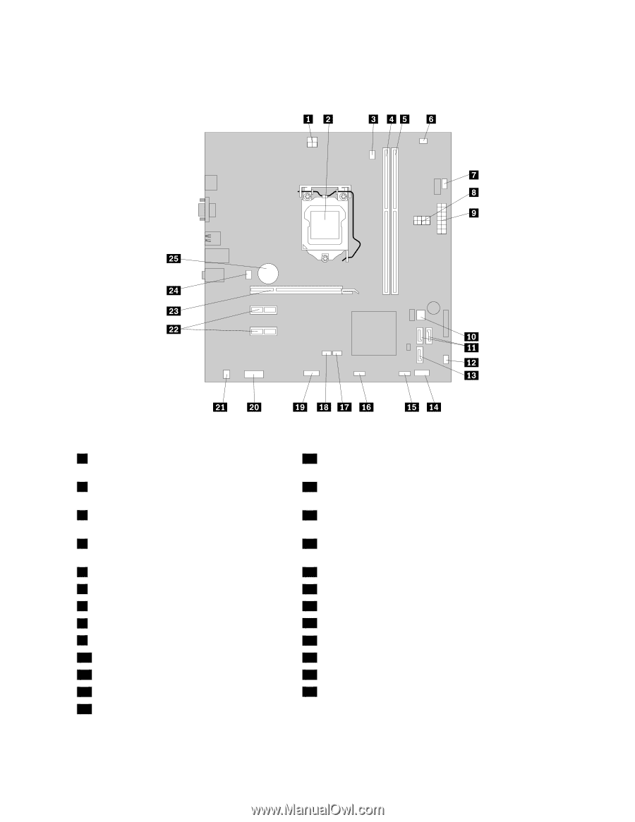
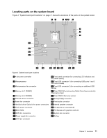
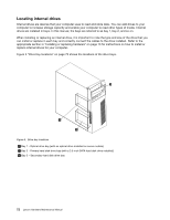
Locating parts on the system board Figure 4 "System board part locations" on page 71 shows the locations of the parts on the system board. Figure 4. System board part locations 1 4-pin power connector 2 Microprocessor 3 Microprocessor fan connector 4 Memory slot 1 (DIMM1) 5 Memory slot 2 (DIMM2) 6 Thermal sensor connector 7 Power fan connector 8 Hard disk drive/ Optical drive power connectors 9 24-pin power connector 10 BIOS ROM 11 SATA 3.0 connectors 12 Power supply fan connector 13 SATA 2.0 connector 14 Front panel connector (for connecting LED indicators and the power switch) 15 Front USB connector 1 (for connecting USB ports 1 and 2 on the front bezel) 16 Front USB connector 2 (for connecting an additional USB device) 17 Clear CMOS (Complementary Metal Oxide Semiconductor) /Recovery jumper 18 Clear CMOS /Recovery jumper 19 Serial (COM2) connector 20 Front audio connector 21 Internal speaker connector 22 PCI Express x1 card slots (2) 23 PCI Express x16 graphics card slot 24 System fan connector 25 Battery Chapter 8. Locations 71
-
 1
1 -
2
-
3
-
4
-
5
-
6
-
7
-
8
-
9
-
10
-
11
-
12
-
13
-
14
-
15
-
16
-
17
-
18
-
19
-
20
-
21
-
22
-
23
-
24
-
25
-
26
-
27
-
28
-
29
-
30
-
31
-
32
-
33
-
34
-
35
-
36
-
37
-
38
-
39
-
40
-
41
-
42
-
43
-
44
-
45
-
46
-
47
-
48
-
49
-
50
-
51
-
52
-
53
-
54
-
55
-
56
-
57
-
58
-
59
-
60
-
61
-
62
-
63
-
64
-
65
-
66
-
67
-
 68
68 -
 69
69 -
 70
70 -
 71
71 -
 72
72 -
 73
73 -
 74
74 -
 75
75 -
 76
76 -
 77
77 -
 78
78 -
79
-
80
-
81
-
82
-
83
-
84
-
85
-
86
-
87
-
88
-
89
-
90
-
91
-
92
-
93
-
94
-
95
-
96
-
97
-
98
-
99
-
100
-
101
-
102
-
103
-
104
-
105
-
106
-
107
-
108
 |
 |