Lenovo B490 Hardware Maintenance Manual - Page 76
Removal steps of DC-in connector and base cover, Applying labels to the base cover
 |
View all Lenovo B490 manuals
Add to My Manuals
Save this manual to your list of manuals |
Page 76 highlights
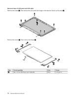
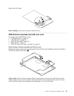
Removal steps of DC-in connector and base cover Remove the screws 1 , and then remove the DC-in connector in the direction shown by the arrow 2 . 11 2 Step 1 Screw (quantity) M2 × 3 mm, flat-head, nylon-coated (2) Color Black Torque 1.85 kgf-cm Applying labels to the base cover The new base cover is shipped with a kit containing labels of several kinds. Apply those labels listed when you replace the base cover. For the labels which are not shipped with the new base cover, peel them off from the old base cover, and adhere them to the new one. Note: If you replace a part with the Windows Certificate of Authentication (COA) label 12 , return the old part with the label attached to the customer. Otherwise, you can provide the customer with a letter, stating the original location of the label on the computer and the information on the label, such as the part number, serial number, and product key. The new base cover FRU is shipped with a kit containing labels of several kinds. The following illustration shows the correct location of each label. 70 Hardware Maintenance Manual
-
 1
1 -
2
-
3
-
4
-
5
-
6
-
7
-
8
-
9
-
10
-
11
-
12
-
13
-
14
-
15
-
16
-
17
-
18
-
19
-
20
-
21
-
22
-
23
-
24
-
25
-
26
-
27
-
28
-
29
-
30
-
31
-
32
-
33
-
34
-
35
-
36
-
37
-
38
-
39
-
40
-
41
-
42
-
43
-
44
-
45
-
46
-
47
-
48
-
49
-
50
-
51
-
52
-
53
-
54
-
55
-
56
-
57
-
58
-
59
-
60
-
61
-
62
-
63
-
64
-
65
-
66
-
67
-
68
-
69
-
70
-
 71
71 -
 72
72 -
 73
73 -
 74
74 -
 75
75 -
 76
76 -
 77
77 -
 78
78 -
 79
79 -
 80
80 -
 81
81 -
82
-
83
-
84
-
85
-
86
-
87
-
88
-
89
-
90
-
91
-
92
-
93
-
94
-
95
-
96
-
97
-
98
-
99
-
100
-
101
-
102
 |
 |
