Lenovo C50-30 Lenovo C50-30 All-In-One Computer Hardware Maintenance Manual - Page 47
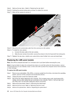
Step 10. Remove the EMI cover. Refer to Removing the EMI cover.
 |
View all Lenovo C50-30 manuals
Add to My Manuals
Save this manual to your list of manuals |
Page 47 highlights
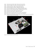
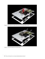
Step 6. Remove the memory modules. Refer to "Replacing a memory module". Step 7. Remove the optical drive. Refer to "Replacing the optical drive". Step 8. Remove the stand holder. Refer to "Removing the stand holder". Step 9. Remove the middle cover. Refer to "Removing the middle cover". Step 10. Remove the EMI cover. Refer to "Removing the EMI cover". Step 11. Remove the heat-sink. Refer to "Replacing the heat-sink". Step 12. Remove the WLAN card. Refer to "Replacing the WLAN card". Step 13. Unplug the following cables from connectors on the motherboard: • Converter cable • System fan power cable • Touch control board cable • Optical drive SATA cable (Red) • Hard disk drive SATA cable (Black) • Hard disk drive and optical drive power cable • Power switch board cable • Speaker system cable • Camera cable • LVDS cable Step 14. Remove the six screws that secure the motherboard to the chassis and lift the motherboard up to remove it. Step 15. To install the new motherboard: a. Line up the holes on the new motherboard with the mounting holes chassis and place the new motherboard into position. Chapter 7. Replacing hardware 41
-
 1
1 -
2
-
3
-
4
-
5
-
6
-
7
-
8
-
9
-
10
-
11
-
12
-
13
-
14
-
15
-
16
-
17
-
18
-
19
-
20
-
21
-
22
-
23
-
24
-
25
-
26
-
27
-
28
-
29
-
30
-
31
-
32
-
33
-
34
-
35
-
36
-
37
-
38
-
39
-
40
-
41
-
 42
42 -
 43
43 -
 44
44 -
 45
45 -
 46
46 -
 47
47 -
 48
48 -
 49
49 -
 50
50 -
 51
51 -
 52
52 -
53
-
54
-
55
-
56
-
57
-
58
-
59
-
60
-
61
-
62
-
63
-
64
-
65
 |
 |
