Lenovo C50-30 Lenovo C50-30 All-In-One Computer Hardware Maintenance Manual - Page 51
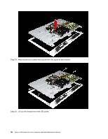
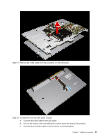
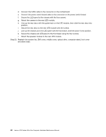
Step 16. Disconnect the LVDS cable from the connector on the motherboard.
 |
View all Lenovo C50-30 manuals
Add to My Manuals
Save this manual to your list of manuals |
Page 51 highlights
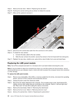
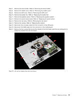
Step 7. Remove the stand holder. Refer to "Removing the stand holder". Step 8. Remove the middle cover. Refer to "Removing the middle cover". Step 9. Remove the EMI cover. Refer to "Removing the EMI cover". Step 10. Remove the system fan. Refer to "Replacing the system fan". Step 11. Remove the speaker system. Refer to "Replacing the speaker system". Step 12. Remove the power switch board. Refer to "Replacing the power switch Step 13. Remove the rear deco. Refer to "Removing the rear deco". Step 14. Remove the camera. Refer to "Replacing the camera". Step 15. Disconnect the converter cable from the connector on the LED panel. Step 16. Disconnect the LVDS cable from the connector on the motherboard. Step 17. Remove the four screws that secure the chassis to the front bezel, push the six locking pins to release the chassis from the front bezel. Step 18. Lift up the chassis from the front bezel. Chapter 7. Replacing hardware 45
-
 1
1 -
2
-
3
-
4
-
5
-
6
-
7
-
8
-
9
-
10
-
11
-
12
-
13
-
14
-
15
-
16
-
17
-
18
-
19
-
20
-
21
-
22
-
23
-
24
-
25
-
26
-
27
-
28
-
29
-
30
-
31
-
32
-
33
-
34
-
35
-
36
-
37
-
38
-
39
-
40
-
41
-
42
-
43
-
44
-
45
-
 46
46 -
 47
47 -
 48
48 -
 49
49 -
 50
50 -
 51
51 -
 52
52 -
 53
53 -
 54
54 -
 55
55 -
 56
56 -
57
-
58
-
59
-
60
-
61
-
62
-
63
-
64
-
65
 |
 |
