Lenovo PC 300 Hardware Maintenance Manual (HMM) for Aptiva, IBM PC300, and Net - Page 111

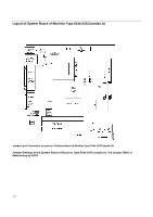
Parts/Test Point Locations, Jumper Settings of the System Board of Machine Types 2194 Italy

Page 111 highlights

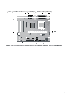
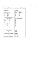
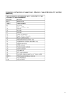
Parts/Test Point Locations Parts/Test Point Locations ...111 Introduction ...112 Layout of System Board of Machine Types 2194 (Italy), 2197 and 6344 (EMEA/AP 113 Jumper Settings of the System Board of Machine Types 2194 (Italy), 2197 and 6344 (EMEA/AP 114 Connectors and Functions of System Board of Machine Types 2194 (Italy), 2197 and 6344 (EMEA/AP)..... 115 Layout of System Board of Machine Type 6344 (US/Canada/LA 116 Connectors and Functions of System Board of Machine Type 6344 (US/Canada/LA 117 Layout of System Board of Machine Types 2193 and 2196 118 Jumper Settings of the System Board of Machine Types 2193 and 2196 119 Connectors and Functions of System Board of Machine Types 2193 and 2196 120 Layout of System Board of Machine Types 2194 and 6345 121 Jumper and Connector Settings of System Board of Machine Types 2194 and 6345 122 Power Supply Cable Connector Specifications ...127 Main Output Pin Assignment...128 Factory-Installed Modem Card Layout ...130 Factory-Installed Modem Card Connector Functions 130 3.5-In. Hard Disk Drive Jumper Locations & Settings 131 CD-ROM Drive ...132 CD-ROM Emergency-exit ...132 CD-ROM Drive Rear Panel Connectors and Features 133 CD-ROM Drive Jumper Settings ...133 DIMM Configurations ...134 System Board Connector Pin Signals ...135 Monitor Port Signals...135 Serial Port Signals ...135 Parallel Port Signals...135 Mouse Port Signals ...135 Keyboard Port Signals ...136 Diskette Drive Cable Connector Signals ...137 IDE Cable Connector Signals ...138 Copyright IBM Corp. 2000 111

  • 1
  • 2
  • 3
  • 4
  • 5
  • 6
  • 7
  • 8
  • 9
  • 10
  • 11
  • 12
  • 13
  • 14
  • 15
  • 16
  • 17
  • 18
  • 19
  • 20
  • 21
  • 22
  • 23
  • 24
  • 25
  • 26
  • 27
  • 28
  • 29
  • 30
  • 31
  • 32
  • 33
  • 34
  • 35
  • 36
  • 37
  • 38
  • 39
  • 40
  • 41
  • 42
  • 43
  • 44
  • 45
  • 46
  • 47
  • 48
  • 49
  • 50
  • 51
  • 52
  • 53
  • 54
  • 55
  • 56
  • 57
  • 58
  • 59
  • 60
  • 61
  • 62
  • 63
  • 64
  • 65
  • 66
  • 67
  • 68
  • 69
  • 70
  • 71
  • 72
  • 73
  • 74
  • 75
  • 76
  • 77
  • 78
  • 79
  • 80
  • 81
  • 82
  • 83
  • 84
  • 85
  • 86
  • 87
  • 88
  • 89
  • 90
  • 91
  • 92
  • 93
  • 94
  • 95
  • 96
  • 97
  • 98
  • 99
  • 100
  • 101
  • 102
  • 103
  • 104
  • 105
  • 106
  • 107
  • 108
  • 109
  • 110
  • 111
  • 112
  • 113
  • 114
  • 115
  • 116
  • 117
  • 118
  • 119
  • 120
  • 121
  • 122
  • 123
  • 124
  • 125
  • 126
  • 127
  • 128
  • 129
  • 130
  • 131
  • 132
  • 133
  • 134
  • 135
  • 136
  • 137
  • 138
  • 139
  • 140
  • 141
  • 142
  • 143
  • 144
  • 145
  • 146
  • 147
  • 148
  • 149
  • 150
  • 151
  • 152
  • 153
  • 154
  • 155
  • 156
  • 157
  • 158
  • 159
  • 160
  • 161
  • 162
  • 163

111
Parts/Test Point Locations
...................................................................................................................................
111
Introduction
.............................................................................................................................................................
112
Layout of System Board of Machine Types 2194 (Italy), 2197 and 6344 (EMEA/AP)
.............................................
113
Jumper Settings of the System Board of Machine Types 2194 (Italy), 2197 and 6344 (EMEA/AP)
...............
114
Connectors and Functions of System Board of Machine Types 2194 (Italy), 2197 and 6344 (EMEA/AP)
.....
115
Layout of System Board of Machine Type 6344 (US/Canada/LA)
..........................................................................
116
Connectors and Functions of System Board of Machine Type 6344 (US/Canada/LA)
..................................
117
Layout of System Board of Machine Types 2193 and 2196
....................................................................................
118
Jumper Settings of the System Board of Machine Types 2193 and 2196
......................................................
119
Connectors and Functions of System Board of Machine Types 2193 and 2196
............................................
120
Layout of System Board of Machine Types 2194 and 6345
....................................................................................
121
Jumper and Connector Settings of System Board of Machine Types 2194 and 6345
...................................
122
Power Supply Cable Connector Specifications
.......................................................................................................
127
Main Output Pin Assignment
..........................................................................................................................
128
Factory-Installed Modem Card Layout
....................................................................................................................
130
Factory-Installed Modem Card Connector Functions
.....................................................................................
130
3.5-In. Hard Disk Drive Jumper Locations & Settings
.............................................................................................
131
CD-ROM Drive
........................................................................................................................................................
132
CD-ROM Emergency-exit
..............................................................................................................................
132
CD-ROM Drive Rear Panel Connectors and Features
...................................................................................
133
CD-ROM Drive Jumper Settings
....................................................................................................................
133
DIMM Configurations
..............................................................................................................................................
134
System Board Connector Pin Signals
.....................................................................................................................
135
Monitor Port Signals
.......................................................................................................................................
135
Serial Port Signals
.........................................................................................................................................
135
Parallel Port Signals
.......................................................................................................................................
135
Mouse Port Signals
........................................................................................................................................
135
Keyboard Port Signals
...................................................................................................................................
136
Diskette Drive Cable Connector Signals
........................................................................................................
137
IDE Cable Connector Signals
........................................................................................................................
138
Copyright IBM Corp. 2000