Lenovo PC 300 Hardware Maintenance Manual (HMM) for Aptiva, IBM PC300, and Net - Page 122
Jumper and Connector Settings of the System Board of Machine Types 2194 and 6345
 |
View all Lenovo PC 300 manuals
Add to My Manuals
Save this manual to your list of manuals |
Page 122 highlights
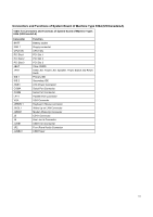
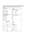
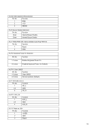
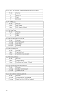
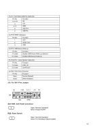
Jumper and Connector Settings of the System Board of Machine Types 2194 and 6345 Table 4-6 Jumper and Connector Settings of the System Board of Machine Types 2194 and 6345 I/O Ports Connector USB IDE1 IDE2 PS/2 FLOPPY COMA LPT VGA ATX Power GAME & Audio USB port. For Primary IDE port. For Secondary IDE port. For PS/2 Mouse & Keyboard port. For Floppy port. For Serial port1 (COM A){Support Modem Ring On}. For LPT port. For VGA Port. For ATX Power Connector. For Game & MIC LINE-IN, LINE-OUT, TEL Port ,CD-IN, AUX-IN, SPDIF OUT (Optional) Socket 370 For Socket 370 Processor installed IR:INFRARED Connector (IR / CIR) Pin No. Function 1 VCC 2 NC 3 IRRX 4 GND 5 IRTX 6 NC 7 CIRRX 8 VCC 9 NC 10 NC CPU FAN: CPU cooling FAN Power Connector Pin No. Function 1 GND. 2 +12V 3 SENSE PWR FAN: Power FAN Connector Pin No. Function 1 GND. 2 +12V 3 SENSE 122
-
 1
1 -
2
-
3
-
4
-
5
-
6
-
7
-
8
-
9
-
10
-
11
-
12
-
13
-
14
-
15
-
16
-
17
-
18
-
19
-
20
-
21
-
22
-
23
-
24
-
25
-
26
-
27
-
28
-
29
-
30
-
31
-
32
-
33
-
34
-
35
-
36
-
37
-
38
-
39
-
40
-
41
-
42
-
43
-
44
-
45
-
46
-
47
-
48
-
49
-
50
-
51
-
52
-
53
-
54
-
55
-
56
-
57
-
58
-
59
-
60
-
61
-
62
-
63
-
64
-
65
-
66
-
67
-
68
-
69
-
70
-
71
-
72
-
73
-
74
-
75
-
76
-
77
-
78
-
79
-
80
-
81
-
82
-
83
-
84
-
85
-
86
-
87
-
88
-
89
-
90
-
91
-
92
-
93
-
94
-
95
-
96
-
97
-
98
-
99
-
100
-
101
-
102
-
103
-
104
-
105
-
106
-
107
-
108
-
109
-
110
-
111
-
112
-
113
-
114
-
115
-
116
-
 117
117 -
 118
118 -
 119
119 -
 120
120 -
 121
121 -
 122
122 -
 123
123 -
 124
124 -
 125
125 -
 126
126 -
 127
127 -
128
-
129
-
130
-
131
-
132
-
133
-
134
-
135
-
136
-
137
-
138
-
139
-
140
-
141
-
142
-
143
-
144
-
145
-
146
-
147
-
148
-
149
-
150
-
151
-
152
-
153
-
154
-
155
-
156
-
157
-
158
-
159
-
160
-
161
-
162
-
163
 |
 |
