Lenovo PC 300 Hardware Maintenance Manual (HMM) for Aptiva, IBM PC300, and Net - Page 68
Factory-Installed Storage Devices, IF THE NUMBER OF DISKETTE, HARD DISK
 |
View all Lenovo PC 300 manuals
Add to My Manuals
Save this manual to your list of manuals |
Page 68 highlights
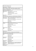
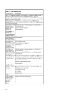
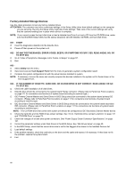
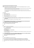
Factory-Installed Storage Devices Use this check procedure to test any factory-installed drives. ATTENTION: The customer may have customized settings in the Setup Utility (other than default settings) on the computer you are servicing. Running the Setup Utility might alter those settings. Take note of the current settings and verify that the customer settings are in place when service is complete. NOTE: If you cannot access the hard disk drive or load a diskette from Drive A or load a CD from the CD-ROM drive, make sure that the BIOS Setup Utility has the startup sequence set with diskette, CD-ROM, and hard disk drives. 001 - START Insert the diagnostics diskette into the diskette drive. Power-off then power-on the system unit. 002 - DO ANY POST MESSAGES, ERROR CODES, BEEPS, OR SYMPTOMS OCCUR? (YES, READ AHEAD. NO, GO TO STEP 003) Go to "Index of Symptoms, Messages, Error Codes, or Beeps" on page 57. End. 003 Select Utility from the menu. Select and execute Tech Support Form from the menu to generate a system configuration report. Compare the system configuration list with the actual devices installed in system. NOTE: If necessary, remove the cover and visually compare the devices installed in the system unit to those shown in the Tech Support Form. 004 - IF THE NUMBER OF DISKETTE, HARD DISK, OR CD-ROM DRIVE IS NOT CORRECT, READ AHEAD; OR GO TO STEP 005. Check the cable installation of all disk drives. Diskette drive should be connected to the system board Floppy connector. (Please refer to Parts/Test Point Locations on page 111 for connectors ona functions of system board according to machine type.) IDE Primary Channel Master and Slave Drives in BIOS Setup should be connected to the system board primary IDE connector. (Please refer to Parts/Test Point Locations on page 111 for connectors ona functions of system board according to machine type) IDE Secondary Channel Master and Slave Drives in BIOS Setup should be connected to the system board secondary IDE connector. (Please refer to Parts/Test Point Locations on page 111 for connectors ona functions of system board according to machine type.) NOTE: The CD-ROM drive that comes with system unit should be configured as IDE Secondary Channel Master device. Check the hard disk and CD-ROM drives jumper settings. See "3.5-In. Hard Disk Drive Jumper Locations" on page 131 and "CD-ROM Drive" on page 73. Check the voltages of all disk drive power connectors. See "Power Supply Cable Connector Specifications" on page 127. Correct the parameter settings under Disk Drives in the BIOS Setup. See "IDE Drives Setup" on page 48. In the BIOS Setup, check that the correct drive size is set for the flagged drive shown in the Installed Devices list. Load default settings. If the problem remains, check the continuity on the drive and the cable and replace it if necessary. If that does not fix the problem, replace the system board. End. 68
-
 1
1 -
2
-
3
-
4
-
5
-
6
-
7
-
8
-
9
-
10
-
11
-
12
-
13
-
14
-
15
-
16
-
17
-
18
-
19
-
20
-
21
-
22
-
23
-
24
-
25
-
26
-
27
-
28
-
29
-
30
-
31
-
32
-
33
-
34
-
35
-
36
-
37
-
38
-
39
-
40
-
41
-
42
-
43
-
44
-
45
-
46
-
47
-
48
-
49
-
50
-
51
-
52
-
53
-
54
-
55
-
56
-
57
-
58
-
59
-
60
-
61
-
62
-
 63
63 -
 64
64 -
 65
65 -
 66
66 -
 67
67 -
 68
68 -
 69
69 -
 70
70 -
 71
71 -
 72
72 -
 73
73 -
74
-
75
-
76
-
77
-
78
-
79
-
80
-
81
-
82
-
83
-
84
-
85
-
86
-
87
-
88
-
89
-
90
-
91
-
92
-
93
-
94
-
95
-
96
-
97
-
98
-
99
-
100
-
101
-
102
-
103
-
104
-
105
-
106
-
107
-
108
-
109
-
110
-
111
-
112
-
113
-
114
-
115
-
116
-
117
-
118
-
119
-
120
-
121
-
122
-
123
-
124
-
125
-
126
-
127
-
128
-
129
-
130
-
131
-
132
-
133
-
134
-
135
-
136
-
137
-
138
-
139
-
140
-
141
-
142
-
143
-
144
-
145
-
146
-
147
-
148
-
149
-
150
-
151
-
152
-
153
-
154
-
155
-
156
-
157
-
158
-
159
-
160
-
161
-
162
-
163
 |
 |