Lenovo PC 300 Hardware Maintenance Manual (HMM) for Aptiva, IBM PC300, and Net - Page 125
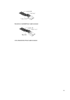
J12: For 2X11 Pins Jumper, Soft PWR: Soft Power Connector, RES: Reset Switch, Open: Normal Operation
 |
View all Lenovo PC 300 manuals
Add to My Manuals
Save this manual to your list of manuals |
Page 125 highlights
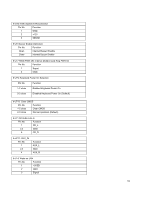
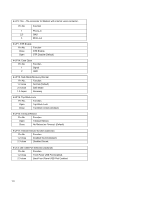
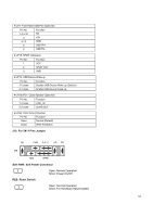
J19: Front Panel USB Port (Optional) Pin No. 1,4,5,10 2 3,7,9 6 8 Function NC +5V GND USB P0+ USB P0- JP18: SPDIF (Optional) Pin No. Function 1 VCC 2 SPDIF OUT 3 GND JP19: USB Device Wake up Pin No. 1-2 close Function Disable USB Device Wake up (Default). 2-3 close Enable USB Device Wake up. JP20/JP21: Quad Speaker (Optional) Pin No. 1-2 close Function LINE_IN 2-3 close QUAD OUT JP24: FWH Write Protection Pin No. Function Open Normal (Default) Close Write Protection. J12: For 2X11 Pins Jumper GD J12 1 PWR P+P−P− HD GN 1 1 1 RES SPKR Soft PWR: Soft Power Connector RES: Reset Switch Open: Normal Operation Short: Power On/Off Open: Normal Operation Short: For Hardware Reset System 125
-
 1
1 -
2
-
3
-
4
-
5
-
6
-
7
-
8
-
9
-
10
-
11
-
12
-
13
-
14
-
15
-
16
-
17
-
18
-
19
-
20
-
21
-
22
-
23
-
24
-
25
-
26
-
27
-
28
-
29
-
30
-
31
-
32
-
33
-
34
-
35
-
36
-
37
-
38
-
39
-
40
-
41
-
42
-
43
-
44
-
45
-
46
-
47
-
48
-
49
-
50
-
51
-
52
-
53
-
54
-
55
-
56
-
57
-
58
-
59
-
60
-
61
-
62
-
63
-
64
-
65
-
66
-
67
-
68
-
69
-
70
-
71
-
72
-
73
-
74
-
75
-
76
-
77
-
78
-
79
-
80
-
81
-
82
-
83
-
84
-
85
-
86
-
87
-
88
-
89
-
90
-
91
-
92
-
93
-
94
-
95
-
96
-
97
-
98
-
99
-
100
-
101
-
102
-
103
-
104
-
105
-
106
-
107
-
108
-
109
-
110
-
111
-
112
-
113
-
114
-
115
-
116
-
117
-
118
-
119
-
 120
120 -
 121
121 -
 122
122 -
 123
123 -
 124
124 -
 125
125 -
 126
126 -
 127
127 -
 128
128 -
 129
129 -
 130
130 -
131
-
132
-
133
-
134
-
135
-
136
-
137
-
138
-
139
-
140
-
141
-
142
-
143
-
144
-
145
-
146
-
147
-
148
-
149
-
150
-
151
-
152
-
153
-
154
-
155
-
156
-
157
-
158
-
159
-
160
-
161
-
162
-
163
 |
 |
125
±
J19: Front Panel USB Port (Optional)
Pin No.
Function
1,4,5,10
NC
2
+5V
3,7,9
GND
6
USB P0+
8
USB P0-
±
JP18: SPDIF (Optional)
Pin No.
Function
1
VCC
2
SPDIF OUT
3
GND
±
JP19: USB Device Wake up
Pin No.
Function
1-2 close
Disable USB Device Wake up (Default).
2-3 close
Enable USB Device Wake up.
±
JP20/JP21: Quad Speaker (Optional)
Pin No.
Function
1-2 close
LINE_IN
2-3 close
QUAD OUT
±
JP24: FWH Write Protection
Pin No.
Function
Open
Normal (Default)
Close
Write Protection.
J12: For 2X11 Pins Jumper
Soft PWR: Soft Power Connector
Open: Normal Operation
Short: Power On/Off
RES: Reset Switch
Open: Normal Operation
Short: For Hardware Reset System
J12
PWR
P+P
−
P
−
HD
RES
SPKR
GN
GD
1
1
1
1