Lenovo PC 300 Hardware Maintenance Manual (HMM) for Aptiva, IBM PC300, and Net - Page 55
Start, How to Diagnose Combined FRUs
 |
View all Lenovo PC 300 manuals
Add to My Manuals
Save this manual to your list of manuals |
Page 55 highlights
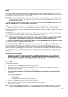
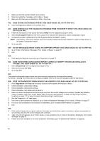
Start This is the entry point for all check procedures. The check procedures use failure symptoms, Power-On Self Test (POST) error codes, or beeps to help determine the defective field replaceable unit (FRU). Follow the suggested check procedures or use the diagnostics diskette to determine the problem FRU. IMPORTANT: Replace FRUs ONLY when it is determined that the error is not a result of software, loose contacts, or dirty component surfaces. Any FRU change should be verified by running a complete test (Diagnostics - All Tests in PCDoctor diagnostics program). This book comes with a diagnostic program diskette. This diskette should be used ONLY with Machine Types 2193, 2194, 2196, 2197, 6344 and 6345. Do not use this diskette on other models. POST error codes and error messages are displayed on the screen after the IBM logo. A beep will precede each error code or message. Please refer to "Index of Symptoms, Messages, Error Codes, or Beeps" on page 57 for additional help. All voltages in the check procedures are positive unless otherwise indicated. Use frame ground for all voltage checks unless otherwise specified. IMPORTANT: There is a voltage selector on the rear panel of the machine. Use a flat-head screwdriver to turn the voltage selector to the voltage setting for the area in which you will be using the system. NOTE: If the check procedures instruct you to replace a FRU and the error message persists, an option adapter card might be causing the failure. Remove all option adapter cards, one at a time, until the error changes or the problem is no longer apparent. The problem may be in the last card that you removed or something associated with it. The Recovery CD contains pre-loaded software that may reinstall the original software and recover the system. Ensure that any data and programs on the hard drive have a backup copy. How to Diagnose Combined FRUs: If an adapter or device consists of more than one FRU, any of the FRUs might cause an error code. Before replacing the device or adapter, remove the FRUs one by one to see if the symptoms change. If a newly replaced FRU does not correct the problem: If you have reached this point of the check procedures and were instructed to replace a FRU but doing so did not correct the problem, reinstall the original FRU and go through "Start" again. If you want to print a copy of a BIOS Setup Utility screen to an attached printer, press Print Screen key, while the screen is displayed. PLEASE READ THE FOLLOWING: Human Error is a cause for concern when applied to check procedures. It exists in every first time set of analysis procedures. It is therefore essential for effective and time-efficient servicing that each stage of every procedure be verified. (For example: When a symptom is found, or when a symptom appears to have been cured; the preceding steps should be repeated for accuracy of analysis.) 001 - START To begin, note the following: Disable the setting of "Quick Power-On Self Test" from BIOS Setup. Disconnect all external cables and devices including speakers and microphone from the system unit, except for the keyboard, mouse, and monitor. Power off the system unit before moving it or when replacing FRUs. Remove all adapter cards, except for the factory-installed modem adapter card and any other IBM factory-installed adapter cards. Disconnect any drives except: • 3.5-in. diskette drive • Hard disk drive • Factory-installed devices (such as a CD-ROM drive) Make sure that all power cords and cables are connected properly. Make sure that the monitor brightness and contrast controls are not turned down. Power on the system unit. NOTE: Some monitors have a detachable system I/O signal cable between the monitor and the system unit. In this case, check this signal cable before replacing the unit. See "Monitor Port Signals" on page 135 for pin identification. 55
-
 1
1 -
2
-
3
-
4
-
5
-
6
-
7
-
8
-
9
-
10
-
11
-
12
-
13
-
14
-
15
-
16
-
17
-
18
-
19
-
20
-
21
-
22
-
23
-
24
-
25
-
26
-
27
-
28
-
29
-
30
-
31
-
32
-
33
-
34
-
35
-
36
-
37
-
38
-
39
-
40
-
41
-
42
-
43
-
44
-
45
-
46
-
47
-
48
-
49
-
 50
50 -
 51
51 -
 52
52 -
 53
53 -
 54
54 -
 55
55 -
 56
56 -
 57
57 -
 58
58 -
 59
59 -
 60
60 -
61
-
62
-
63
-
64
-
65
-
66
-
67
-
68
-
69
-
70
-
71
-
72
-
73
-
74
-
75
-
76
-
77
-
78
-
79
-
80
-
81
-
82
-
83
-
84
-
85
-
86
-
87
-
88
-
89
-
90
-
91
-
92
-
93
-
94
-
95
-
96
-
97
-
98
-
99
-
100
-
101
-
102
-
103
-
104
-
105
-
106
-
107
-
108
-
109
-
110
-
111
-
112
-
113
-
114
-
115
-
116
-
117
-
118
-
119
-
120
-
121
-
122
-
123
-
124
-
125
-
126
-
127
-
128
-
129
-
130
-
131
-
132
-
133
-
134
-
135
-
136
-
137
-
138
-
139
-
140
-
141
-
142
-
143
-
144
-
145
-
146
-
147
-
148
-
149
-
150
-
151
-
152
-
153
-
154
-
155
-
156
-
157
-
158
-
159
-
160
-
161
-
162
-
163
 |
 |