Lenovo ThinkCentre M60e Hardware Maintenance Manual for ThinkCentre M60e - Page 101
Make sure that the microprocessor has been removed from the microprocessor socket. See Replacing
 |
View all Lenovo ThinkCentre M60e manuals
Add to My Manuals
Save this manual to your list of manuals |
Page 101 highlights
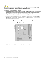
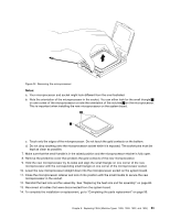
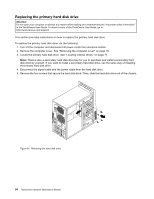
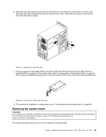
12. Install the new system board into the chassis by aligning the eight mounting studs in the chassis with the corresponding holes in the new system board. Carefully slide the new system board into the chassis until it is secured in place by the mounting studs. Then, install the eight screws to secure the system board. 13. Install the heat sink and fan assembly and connect the heat sink and fan assembly cable to the new system board. See "Replacing the heat sink and fan assembly" on page 88. 14. Install all memory modules and PCI cards removed from the failing system board on the new system board. See "Installing or replacing a memory module" on page 83 and "Installing or replacing a PCI card" on page 81. 15. Reconnect all remaining cables to the system board. See "Locating parts on the system board" on page 76. 16. Install the hard disk drive. See "Replacing the primary hard disk drive" on page 94. 17. To complete the installation or replacement, go to "Completing the parts replacement" on page 99. The failing system board must be returned with a microprocessor socket cover to protect the pins during shipping and handling. To install the microprocessor socket cover: 1. Make sure that the microprocessor has been removed from the microprocessor socket. See "Replacing the microprocessor" on page 91. 2. Close the microprocessor retainer and lock it into position with the small handle. 3. Insert the tabs 1 of the socket cover into the hinged side of the socket. Figure 28. Tabs on the microprocessor socket cover (bottom view) 4. Press the other side of the socket cover downward until the tabs 2 snap into position. Figure 29. Installing the microprocessor socket cover Chapter 8. Replacing FRUs (Machine Types: 1899, 1928, 1932, and 1934) 97
-
 1
1 -
2
-
3
-
4
-
5
-
6
-
7
-
8
-
9
-
10
-
11
-
12
-
13
-
14
-
15
-
16
-
17
-
18
-
19
-
20
-
21
-
22
-
23
-
24
-
25
-
26
-
27
-
28
-
29
-
30
-
31
-
32
-
33
-
34
-
35
-
36
-
37
-
38
-
39
-
40
-
41
-
42
-
43
-
44
-
45
-
46
-
47
-
48
-
49
-
50
-
51
-
52
-
53
-
54
-
55
-
56
-
57
-
58
-
59
-
60
-
61
-
62
-
63
-
64
-
65
-
66
-
67
-
68
-
69
-
70
-
71
-
72
-
73
-
74
-
75
-
76
-
77
-
78
-
79
-
80
-
81
-
82
-
83
-
84
-
85
-
86
-
87
-
88
-
89
-
90
-
91
-
92
-
93
-
94
-
95
-
 96
96 -
 97
97 -
 98
98 -
 99
99 -
 100
100 -
 101
101 -
 102
102 -
 103
103 -
 104
104 -
 105
105 -
 106
106 -
107
-
108
-
109
-
110
-
111
-
112
-
113
-
114
-
115
-
116
-
117
-
118
-
119
-
120
 |
 |
