LevelOne FCS-4041 User Manual - Page 7
Switch/Connector Definition
 |
View all LevelOne FCS-4041 manuals
Add to My Manuals
Save this manual to your list of manuals |
Page 7 highlights
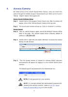
1.4 Switch/Connector Definition There are various connectors located on the Dome Camera's back plate as shown in the figures below. Please refer to the diagrams and tables accompanied with for use of each switch/connector. Outdoor A RJ-45 Connector B ALARM I/O C Power D Micro SD Card Slot E Factory Reset Button F Audio I/O NOTE: DO NOT change the network Speed Dome Camera's Communication Switch factory default settings. 7
-
 1
1 -
 2
2 -
 3
3 -
 4
4 -
 5
5 -
 6
6 -
 7
7 -
 8
8 -
 9
9 -
 10
10 -
 11
11 -
 12
12 -
13
-
14
-
15
-
16
-
17
-
18
-
19
-
20
-
21
-
22
-
23
-
24
-
25
-
26
-
27
-
28
-
29
-
30
-
31
-
32
-
33
-
34
-
35
-
36
-
37
-
38
-
39
-
40
-
41
-
42
-
43
-
44
-
45
-
46
-
47
-
48
-
49
-
50
-
51
-
52
-
53
-
54
-
55
-
56
-
57
-
58
-
59
-
60
-
61
-
62
-
63
-
64
-
65
-
66
-
67
-
68
-
69
-
70
-
71
-
72
-
73
-
74
-
75
-
76
-
77
-
78
-
79
-
80
-
81
 |
 |

7
1.4
Switch/Connector Definition
There are various connectors located on the Dome Camera
’
s back plate as
shown in the figures below.
Please refer to the diagrams and tables accompanied with for use of each
switch/connector.
Outdoor
A
RJ-45 Connector
B
ALARM I/O
C
Power
D
Micro SD Card Slot
E
Factory Reset Button
F
Audio I/O
NOTE:
DO NOT change the network Speed Dome
Camera’s
Communication Switch factory default settings.