LiftMaster EL1SS EL1SS Installation and Programming Manual - Page 5
CARTON INVENTORY, DESCRIPTION OF THE PROCESSOR BOARD, Relay 2 Secondary Output Status LED
 |
View all LiftMaster EL1SS manuals
Add to My Manuals
Save this manual to your list of manuals |
Page 5 highlights
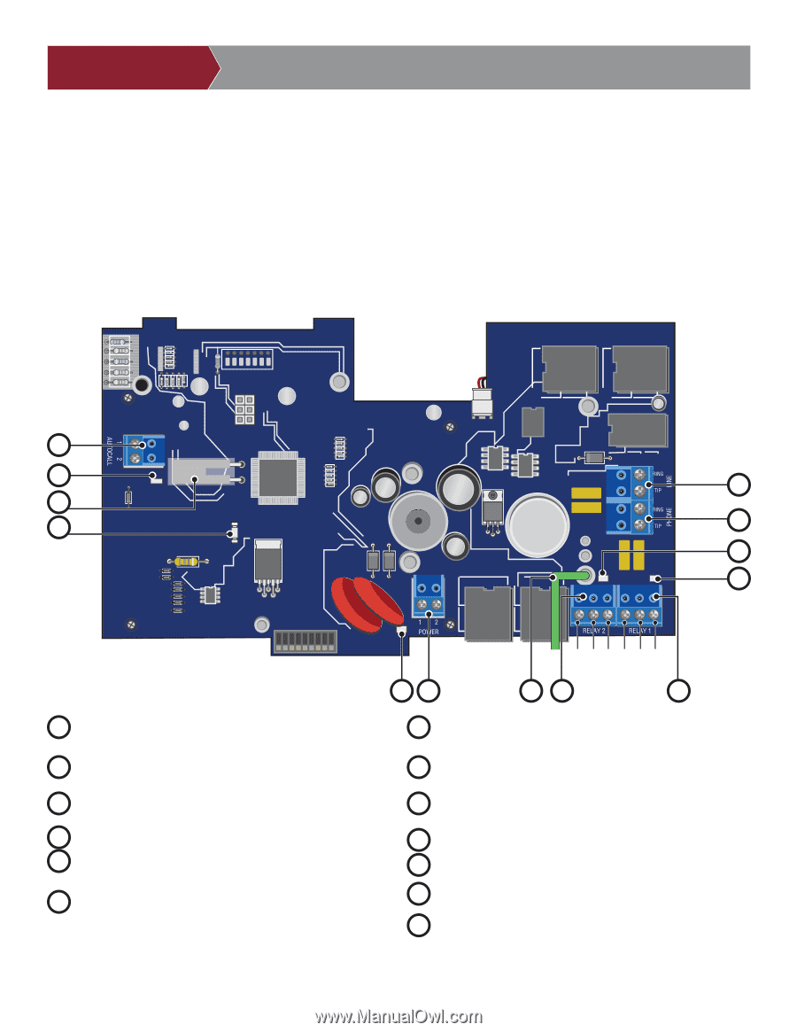
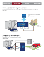
INTRODUCTION INSTALLATION TESTING CARTON INVENTORY Unit (1) Key (1) 12 Vac 20 VA or 16 Vdc 2.5A Plug-In UL Listed Power Transformer (1) Bypass Board (1) Manual (1) DESCRIPTION OF THE PROCESSOR BOARD PROGRAMMING 1 9 6 7 5 10 13 12 COM NO NC COM NO NC 11 2 8 3 4 1 Autocall Input: Connector for accessory device to trigger home dialing. 2 Power Connector: 12 Volt AC power input. 3 Relay 2 Output: Form "C" secondary control relay. 4 Relay 1 Output: Form "C" primary control relay. 5 Phone Output: Telephone return connection to home or office phones. 6 Line Input: Telephone input connection from "Telco" service provider. 7 Tamper Switch 8 Ground Wire: Wire must be connected to positive earth ground. See Earth Ground Rod. 9 Status LED 10 Voice Data Send Status LED 11 Power Status LED 12 Relay 1 (Primary) Output Status LED 13 Relay 2 (Secondary) Output Status LED 3
-
 1
1 -
 2
2 -
 3
3 -
 4
4 -
 5
5 -
 6
6 -
 7
7 -
 8
8 -
 9
9 -
 10
10 -
 11
11 -
12
-
13
-
14
-
15
-
16
-
17
-
18
-
19
-
20
-
21
-
22
-
23
-
24
-
25
-
26
-
27
-
28
-
29
-
30
-
31
-
32
-
33
-
34
-
35
-
36
-
37
-
38
-
39
-
40
-
41
-
42
-
43
-
44
-
45
-
46
-
47
-
48
 |
 |