LiftMaster EL1SS EL1SS Installation and Programming Manual - Page 6
Installation, MOUNT THE UNIT, OVERVIEW OF TELCO WIRING, Function, Old Color Standard
 |
View all LiftMaster EL1SS manuals
Add to My Manuals
Save this manual to your list of manuals |
Page 6 highlights
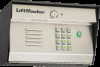
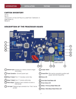
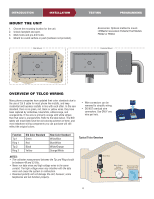
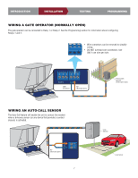
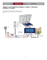
INTRODUCTION INSTALLATION MOUNT THE UNIT 1. Choose the mounting location for the unit. 2. Unlock faceplate and open. 3. Mark holes and pre-drill holes. 4. Mount to a solid surface or post (hardware not provided). Wall Mount TESTING PROGRAMMING Accessories: Optional method to mount. LiftMaster Gooseneck Pedestal Post Models PED42 or PED64 Pedestal Mount OVERVIEW OF TELCO WIRING Many phone companies have updated their color standards due to the use of Cat 5 cable for most phone line installs, and keep residential and business installs in line with each other. In the new standard, there is no green, red, black or yellow wires, they have been replaced by white/blue, blue/white, white/orange, and orange/white. If the wire is primarily orange with white stripes then that color is orange/white. Refer to the table below. The NID labels will most likely have the old coloring scheme on them, and most telephone wiring components you can purchase will still reflect the original colors. • Wire connectors can be removed to simplify wiring. • DO NOT overload wire connectors. Use ONLY one wire per hole. Function Tip 1 Ring 1 Tip 2 Ring 2 Old Color Standard Green Red Black Yellow New Color Standard White/Blue Blue/White White/Orange Orange/White NOTES: • The voltmeter measurement between the Tip and Ring should be between 48 and 53 Vdc. • Never run data wires and high voltage wires in the same conduit. The high voltage wires may interfere with the data wires and cause the system to malfunction. • Reversed polarity will not damage the unit, however, some telephones will not function properly. Typical Telco Overview Home Phone 12:00 AM Dec. 31 MENU REDIAL TALK OFF FLASH 1 2 3 &') ABC DEF 4 5 6 GHI JKL MON 7 8 9 PQRS TUV WXYZ 0 # OPER Ring Tip Alarm System Position (Not Provided) Telco Entrance Box Demarcation Point 4
-
 1
1 -
 2
2 -
 3
3 -
 4
4 -
 5
5 -
 6
6 -
 7
7 -
 8
8 -
 9
9 -
 10
10 -
 11
11 -
 12
12 -
13
-
14
-
15
-
16
-
17
-
18
-
19
-
20
-
21
-
22
-
23
-
24
-
25
-
26
-
27
-
28
-
29
-
30
-
31
-
32
-
33
-
34
-
35
-
36
-
37
-
38
-
39
-
40
-
41
-
42
-
43
-
44
-
45
-
46
-
47
-
48
 |
 |