MSI 915GLM4 User Guide - Page 17
Hardware Setup
 |
View all MSI 915GLM4 manuals
Add to My Manuals
Save this manual to your list of manuals |
Page 17 highlights
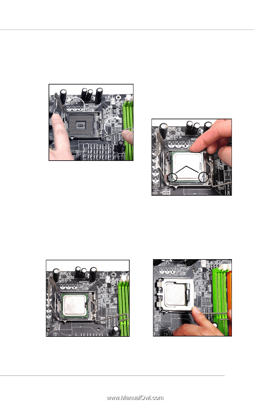
Hardware Setup 5. Lift the load lever up and open the load plate. 6. After confirming the CPU direction for correction mating, put down the CPU in the socket housing frame. Be sure to grape on the edge of the substrate. Note that the alignment keys are matched. alignment key 7. Visually inspect if the CPU is seated well into the socket. If not, take out the CPU with purely vertical motion and reload it again. 8. Rotate the load plate onto the p ac kage. 2-5
-
 1
1 -
2
-
3
-
4
-
5
-
6
-
7
-
8
-
9
-
10
-
11
-
 12
12 -
 13
13 -
 14
14 -
 15
15 -
 16
16 -
 17
17 -
 18
18 -
 19
19 -
 20
20 -
 21
21 -
 22
22 -
23
-
24
-
25
-
26
-
27
-
28
-
29
-
30
-
31
-
32
-
33
-
34
-
35
-
36
-
37
-
38
-
39
-
40
-
41
-
42
-
43
-
44
-
45
-
46
-
47
-
48
-
49
-
50
-
51
-
52
-
53
-
54
-
55
-
56
-
57
-
58
-
59
-
60
-
61
-
62
-
63
-
64
-
65
-
66
-
67
-
68
-
69
-
70
-
71
-
72
-
73
-
74
-
75
-
76
-
77
-
78
-
79
-
80
-
81
-
82
-
83
-
84
-
85
-
86
-
87
-
88
-
89
-
90
-
91
-
92
-
93
-
94
-
95
-
96
-
97
-
98
-
99
-
100
-
101
-
102
-
103
-
104
-
105
 |
 |
2-5
Hardware Setup
6. After confirming the CPU di-
rection for correction mating,
put down the CPU in the
socket housing frame. Be sure
to grape on the edge of the
substrate. Note that the align-
ment
keys are matched.
8. Rotate the load plate onto the
package.
7. Visually inspect if the CPU is
seated well into the socket. If not,
take out the CPU with purely verti-
cal motion and reload it again.
alignment
key
5. Lift the load lever up and open the
load plate.