MSI 915GLM4 User Guide - Page 30
Front Panel Audio Connector: JAUD1
 |
View all MSI 915GLM4 manuals
Add to My Manuals
Save this manual to your list of manuals |
Page 30 highlights
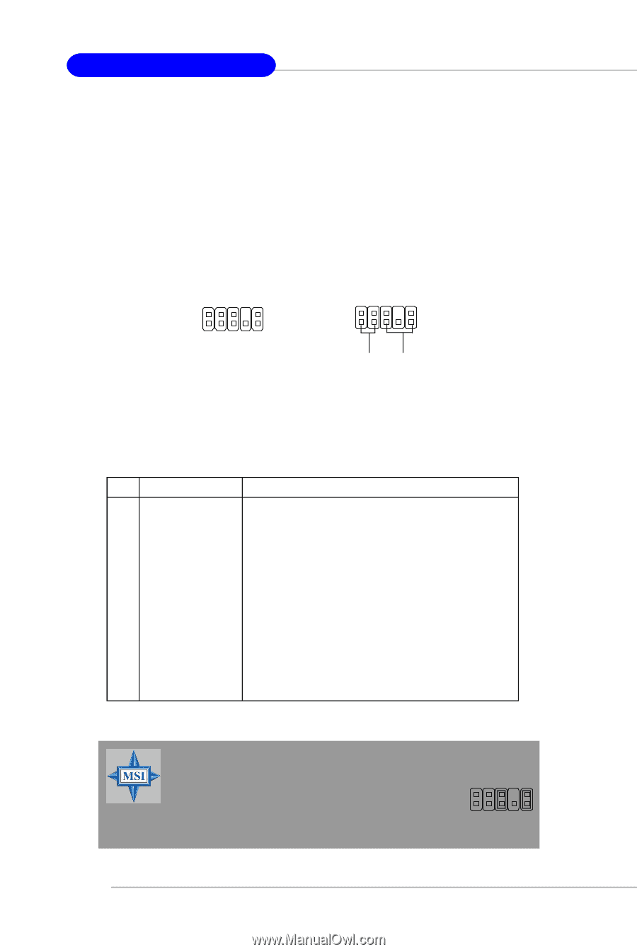
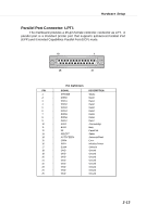
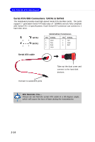
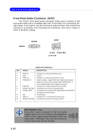
M S-7133 M -ATX M ainboard Front Panel Audio Connector: JAUD1 The JAUD1 front panel audio connector allows you to connect to the front panel audio and is compliant with Intel® Front Panel I/O Connectivity Design Guide. If you want to use the front panel audio function, first connect the connectors according to the following pin definitions, then select Azalia or AC97 in the BIOS setting. JAUD1 Azalia 2 10 1 9 AC97 2 4 6 8 10 5 91 7 3 Front Front Mic Line-out JAUD1 Pin Definition PIN SIGNAL DESCRIPTION 1 PORT 1L Analog Port 1 - Left channel (Front mic L) 2 GND Ground 3 PORT 1R Analog Port 1 - Right channel (Front mic R) 4 PRESENCE# Active low signal - signals BIOS that a High Definition Audio dongle is connected to the analog header. PRESENCE# = 0 when a High Definition Audio dongle is connected. 5 PORT 2R Analog Port 2 - Right channel (Front line-out R) 6 SENSE1_RETIRN Jack detection return from front panel JACK1 7 SENSE_SEND Jack detection sense line from the High Definition Audio CODEC jack detection resistor network 8 KEY Connector Key 9 PORT 2L Analog Port 2 - Left channel (Front line-out L) 10 SENSE2_RETIRN Jack detection return from front panel JACK2 2-18 MSI Reminds You... If you don't want to connect to the front audio header, pins 5 & 6, 9 & 10 have to be jumpered in order to have signal output directed to the rear audio ports. Otherwise, the Line-Out connector on the back panel will not function. 6 10 59
-
 1
1 -
2
-
3
-
4
-
5
-
6
-
7
-
8
-
9
-
10
-
11
-
12
-
13
-
14
-
15
-
16
-
17
-
18
-
19
-
20
-
21
-
22
-
23
-
24
-
 25
25 -
 26
26 -
 27
27 -
 28
28 -
 29
29 -
 30
30 -
 31
31 -
 32
32 -
 33
33 -
 34
34 -
 35
35 -
36
-
37
-
38
-
39
-
40
-
41
-
42
-
43
-
44
-
45
-
46
-
47
-
48
-
49
-
50
-
51
-
52
-
53
-
54
-
55
-
56
-
57
-
58
-
59
-
60
-
61
-
62
-
63
-
64
-
65
-
66
-
67
-
68
-
69
-
70
-
71
-
72
-
73
-
74
-
75
-
76
-
77
-
78
-
79
-
80
-
81
-
82
-
83
-
84
-
85
-
86
-
87
-
88
-
89
-
90
-
91
-
92
-
93
-
94
-
95
-
96
-
97
-
98
-
99
-
100
-
101
-
102
-
103
-
104
-
105
 |
 |