MSI 915GLM4 User Guide - Page 32
IEEE 1394 Connectors: J1394 optional, IrDA Infrared Module Header: JIR1
 |
View all MSI 915GLM4 manuals
Add to My Manuals
Save this manual to your list of manuals |
Page 32 highlights
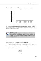
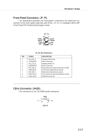
M S-7133 M -ATX M ainboard IEEE 1394 Connectors: J1394 (optional) The mainboard provides one 1394 pin headers that allow you to connect IEEE 1394 ports via an external IEEE1394 bracket. 1 2 9 10 J1394 Pin Definition PIN SIGNAL PIN 1 TPA+ 2 3 Ground 4 5 TPB+ 6 7 Cable power 8 9 Key (no pin) 10 SIGNAL TPAGround TPBCable power Ground IrDA Infrared Module Header: JIR1 The connector allows you to connect to IrDA Infrared module. You must configure the setting through the BIOS setup to use the IR function. JIR1 is compliant with Intel® Front Panel I/O Connectivity Design Guide. JIR1 Pin Definition 5 1 6 2 JIR1 Pin Signal Pin 1 NC 2 3 VCC5 4 5 IRTX 6 Signal NC GND IRRX 2-20
-
 1
1 -
2
-
3
-
4
-
5
-
6
-
7
-
8
-
9
-
10
-
11
-
12
-
13
-
14
-
15
-
16
-
17
-
18
-
19
-
20
-
21
-
22
-
23
-
24
-
25
-
26
-
 27
27 -
 28
28 -
 29
29 -
 30
30 -
 31
31 -
 32
32 -
 33
33 -
 34
34 -
 35
35 -
 36
36 -
 37
37 -
38
-
39
-
40
-
41
-
42
-
43
-
44
-
45
-
46
-
47
-
48
-
49
-
50
-
51
-
52
-
53
-
54
-
55
-
56
-
57
-
58
-
59
-
60
-
61
-
62
-
63
-
64
-
65
-
66
-
67
-
68
-
69
-
70
-
71
-
72
-
73
-
74
-
75
-
76
-
77
-
78
-
79
-
80
-
81
-
82
-
83
-
84
-
85
-
86
-
87
-
88
-
89
-
90
-
91
-
92
-
93
-
94
-
95
-
96
-
97
-
98
-
99
-
100
-
101
-
102
-
103
-
104
-
105
 |
 |
2-20
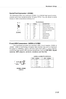
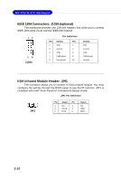
MS-7133 M-ATX Mainboard
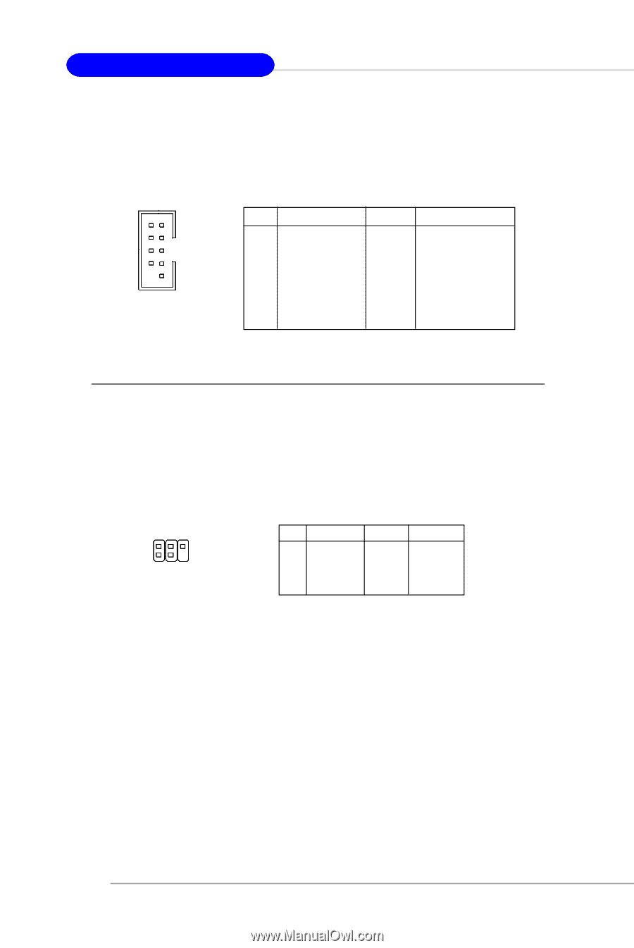
IEEE 1394 Connectors: J1394 (optional)
The mainboard provides one 1394 pin headers that allow you to connect
IEEE 1394 ports via an external IEEE1394 bracket.
Pin Definition
PIN
SIGNAL
PIN
SIGNAL
1
TPA+
2
TPA-
3
Ground
4
Ground
5
TPB+
6
TPB-
7
Cable power
8
Cable power
9
Key (no pin)
10
Ground
J1394
9
10
1
2
IrDA Infrared Module Header: JIR1
The connector allows you to connect to IrDA Infrared module. You must
configure the setting through the BIOS setup to use the IR function. JIR1 is
compliant with Intel
®
Front Panel I/O Connectivity Design Guide.
JIR1 Pin Definition
Pin
Signal
Pin
Signal
1
NC
2
NC
3
VCC5
4
GND
5
IRTX
6
IRRX
JIR1
6
5
2
1