MSI 915GLM4 User Guide - Page 22
Back Panel
 |
View all MSI 915GLM4 manuals
Add to My Manuals
Save this manual to your list of manuals |
Page 22 highlights
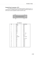
M S-7133 M -ATX M ainboard Back Panel The back panel provides the following connectors: M ou se IEEE1394 Parallel LAN L-In Surround Center/ Subwoofer Keyboard USB Ports COM port VGA port USB Ports L-Out S/PDIF (915G/GV/GL) Mic Out Mouse/Keyboard Connector The mainboard provides a standard PS/2® mouse/keyboard mini DIN connector for attaching a PS/2® mouse/keyboard. You can plug a PS/2® mouse/ keyboard directly into this connector. The connector location and pin assignments are as follows: 6 5 4 3 2 1 PS/2 Mouse / Keyboard (6-pin Female) Pin Definition PIN SIGNAL DESCRIPTION 1 Mouse/Keyboard Data Mouse/Keyboard data 2 NC No connection 3 GND Ground 4 VCC +5V 5 Mouse/KeyboardClock Mouse/Keyboardclock 6 NC No connection VGA Connector (915G/GV/GL) The mainboard provides a DB 15-pin female connector to connect a VGA monitor. 5 1 15 11 VGA Connector (DB 15-pin) Pin Signal Description Pin Signal Description 1 RED 2 GREEN 3 BLUE 4 N/C 5 GND 6 GND 7 GND 8 GND 9 +5V 10 GND 11 N/C 12 SDA 13 Horizontal Sync 14 Vertical Sync 15 SCL 2-10
-
 1
1 -
2
-
3
-
4
-
5
-
6
-
7
-
8
-
9
-
10
-
11
-
12
-
13
-
14
-
15
-
16
-
 17
17 -
 18
18 -
 19
19 -
 20
20 -
 21
21 -
 22
22 -
 23
23 -
 24
24 -
 25
25 -
 26
26 -
 27
27 -
28
-
29
-
30
-
31
-
32
-
33
-
34
-
35
-
36
-
37
-
38
-
39
-
40
-
41
-
42
-
43
-
44
-
45
-
46
-
47
-
48
-
49
-
50
-
51
-
52
-
53
-
54
-
55
-
56
-
57
-
58
-
59
-
60
-
61
-
62
-
63
-
64
-
65
-
66
-
67
-
68
-
69
-
70
-
71
-
72
-
73
-
74
-
75
-
76
-
77
-
78
-
79
-
80
-
81
-
82
-
83
-
84
-
85
-
86
-
87
-
88
-
89
-
90
-
91
-
92
-
93
-
94
-
95
-
96
-
97
-
98
-
99
-
100
-
101
-
102
-
103
-
104
-
105
 |
 |
