MSI MS 7021 User Guide - Page 23
Back Panel & Power Supply - ms
 |
UPC - 816909004694
View all MSI MS 7021 manuals
Add to My Manuals
Save this manual to your list of manuals |
Page 23 highlights
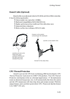
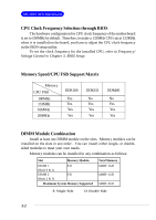
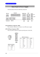
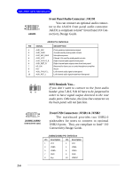
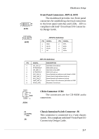
MS-7021 ATX Mainboard Back Panel & Power Supply The back panel provides the following connectors: Mouse Parallel SPDIF-Out LAN L-in L-out Keyboard COM A USB USB MIC ATX 20-Pin Power Connector: JWR1 This connector allows you to connect to an ATX power supply. ATX 12V Power Connector: JPW1 This 12V power connector is used to provide power to the CPU. 10 20 3 4 1 2 JPW1 1 11 JWR1 JPW1 Pin Definition PIN SIGNAL 1 GND 2 GND 3 12V 4 12V JWR1 Pin Definition PIN SIGNAL PIN 1 3.3V 11 2 3.3V 12 3 GND 13 4 5V 14 5 GND 15 6 5V 16 7 GND 17 8 PW_OK 18 9 5V_SB 19 10 12V 20 SIGNAL 3.3V -12V GND PS_ON GND GND GND -5V 5V 5V 2-4
-
 1
1 -
2
-
3
-
4
-
5
-
6
-
7
-
8
-
9
-
10
-
11
-
12
-
13
-
14
-
15
-
16
-
17
-
 18
18 -
 19
19 -
 20
20 -
 21
21 -
 22
22 -
 23
23 -
 24
24 -
 25
25 -
 26
26 -
 27
27 -
 28
28 -
29
-
30
-
31
-
32
-
33
-
34
-
35
-
36
-
37
-
38
-
39
-
40
-
41
-
42
-
43
-
44
-
45
-
46
-
47
-
48
-
49
-
50
-
51
-
52
-
53
-
54
-
55
-
56
-
57
-
58
-
59
-
60
-
61
-
62
-
63
-
64
-
65
-
66
-
67
-
68
-
69
 |
 |

2-4
MS-7021 ATX Mainboard
The back panel provides the following connectors:
Back Panel & Power Supply
ATX 20-Pin Power Connector: JWR1
This connector allows you to connect to an ATX power supply.
ATX 12V Power Connector: JPW1
This 12V power connector is used to provide power to the CPU.
PIN
SIGNAL
11
3.3V
12
-12V
13
GND
14
PS_ON
15
GND
16
GND
17
GND
18
-5V
19
5V
20
5V
PIN
SIGNAL
1
3.3V
2
3.3V
3
GND
4
5V
5
GND
6
5V
7
GND
8
PW_OK
9
5V_SB
10
12V
JWR1 Pin Definition
PIN
SIGNAL
1
GND
2
GND
3
12V
4
12V
JPW1 Pin Definition
JPW1
1
3
4
2
JWR1
10
1
20
11
Mouse
Keyboard
USB
Parallel
COM A
LAN
USB
L-out
L-in
MIC
SPDIF-Out