MSI MS 7021 User Guide - Page 26
Front Panel Connectors: JFP1 & JFP2, CD-In Connector: JCD1, Chassis Intrusion Switch Connector: - audio
 |
UPC - 816909004694
View all MSI MS 7021 manuals
Add to My Manuals
Save this manual to your list of manuals |
Page 26 highlights
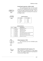
2 10 1 9 JFP1 2 8 1 7 JFP2 Hardware Setup Front Panel Connectors: JFP1 & JFP2 The mainboard provides two front panel connectors for establishing electrical connection to the front panel switches and LEDs. JFP1 is compliant with Intel® Front Panel I/O Connectivity Design Guide. JFP2 Pin Definition PIN SIGNAL 1 GND 3 SLED 5 PLED 7 NC PIN SIGNAL 2 SPK- 4 BUZ+ 6 BUZ- 8 SPK+ JFP1 Pin Definition PIN SIGNAL 1 HD_LED_P 2 FP PW R/SLP 3 HD_LED_N 4 FP PW R/SLP 5 RST_SW _N 6 PWR_SW_P 7 RST_SW_P 8 PW R_SW _N 9 RSVD_DNU DESCRIPTION Hard disk LED pull-up MSG LED pull-up Hard disk active LED MSG LED pull-up Reset Switch low reference pull-down to GND Power Switch high reference pull-up Reset Switch high reference pull-up Power Switch low reference pull-down to GND Reserved. Do not use. R GND L JCD1 CD-In Connector: JCD1 The connectors are for CD-ROM audio connectors. CINTRU GND J6 Chassis Intrusion Switch Connector: J6 This connector is connected to a 2-pin chassis switch. J6 is compliant with Intel® Front Panel I/O Connectivity Design Guide. 2-7
-
 1
1 -
2
-
3
-
4
-
5
-
6
-
7
-
8
-
9
-
10
-
11
-
12
-
13
-
14
-
15
-
16
-
17
-
18
-
19
-
20
-
 21
21 -
 22
22 -
 23
23 -
 24
24 -
 25
25 -
 26
26 -
 27
27 -
 28
28 -
 29
29 -
 30
30 -
 31
31 -
32
-
33
-
34
-
35
-
36
-
37
-
38
-
39
-
40
-
41
-
42
-
43
-
44
-
45
-
46
-
47
-
48
-
49
-
50
-
51
-
52
-
53
-
54
-
55
-
56
-
57
-
58
-
59
-
60
-
61
-
62
-
63
-
64
-
65
-
66
-
67
-
68
-
69
 |
 |
