MSI MS 7021 User Guide - Page 25
Front Panel Audio Connector: JAUD1, Front USB Connectors: JUSB1 & JUSB2 - spec
 |
UPC - 816909004694
View all MSI MS 7021 manuals
Add to My Manuals
Save this manual to your list of manuals |
Page 25 highlights
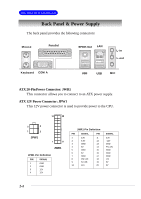
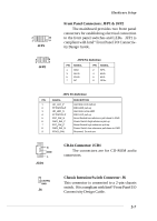
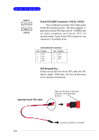
MS-7021 ATX Mainboard 9 1 10 2 JAUD1 Front Panel Audio Connector: JAUD1 You can connect an optional audio connector to the JAUD1 front panel audio connector. JAUD1 is compliant to Intel® Front Panel I/O Connectivity Design Guide. JAUD1 Pin Definition PIN SIGNAL DESCRIPTION 1 AUD_MIC Front panel microphone input signal 2 AUD_GND Ground used by analog audio circuits 3 AUD_MIC_BIAS Microphone power 4 AUD_VCC Filtered +5V used by analog audio circuits 5 AUD_FPOUT_R Right channel audiosignal to front panel 6 AUD_RET_R Right channel audio signal return from front panel 7 HP_ON Reserved for future use to control headphone amplifier 8 KEY No pin 9 AUD_FPOUT_L Left channel audio signal to front panel 10 AUD_RET_L Left channel audio signal return from front panel 95 10 6 MSI Reminds You... If you don't want to connect to the front audio header, pins 5 & 6, 9 & 10 have to be jumpered in order to have signal output directed to the rear audio ports. Otherwise, the Line-Out connector on the back panel will not function. 2 10 1 9 JUSB1/JUSB2 (USB 2.0/Intel spec) Front USB Connectors: JUSB1 & JUSB2 The mainboard provides two USB2.0 pinheaders for users to connect to optional USB2.0 ports. They are compliant to Intel® I/O Connectivity Design Guide. 2-6 JUSB1/JUSB2 Pin Definition Pin Description Pin Description 1 VCC 2 VCC 3 USB0- 4 USB1- 5 USB0+ 6 USB1+ 7 GND 8 GND 9 Key 10 USBOC
-
 1
1 -
2
-
3
-
4
-
5
-
6
-
7
-
8
-
9
-
10
-
11
-
12
-
13
-
14
-
15
-
16
-
17
-
18
-
19
-
 20
20 -
 21
21 -
 22
22 -
 23
23 -
 24
24 -
 25
25 -
 26
26 -
 27
27 -
 28
28 -
 29
29 -
 30
30 -
31
-
32
-
33
-
34
-
35
-
36
-
37
-
38
-
39
-
40
-
41
-
42
-
43
-
44
-
45
-
46
-
47
-
48
-
49
-
50
-
51
-
52
-
53
-
54
-
55
-
56
-
57
-
58
-
59
-
60
-
61
-
62
-
63
-
64
-
65
-
66
-
67
-
68
-
69
 |
 |
