Mackie PPM1012 Owner's Manual - Page 11
Connection - owner manual for
 |
View all Mackie PPM1012 manuals
Add to My Manuals
Save this manual to your list of manuals |
Page 11 highlights
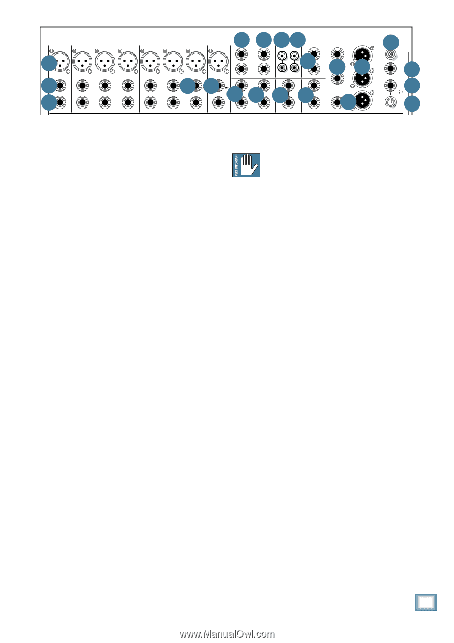
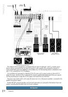
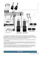
Owner's Manual 10 11 13 14 21 5 6 11 MIC 1 LINE (BAL/UNBAL) INSERT MIC 2 LINE (BAL/UNBAL) INSERT MIC 3 LINE (BAL/UNBAL) INSERT MIC 4 LINE (BAL/UNBAL) INSERT MIC 5 LINE (BAL/UNBAL) INSERT MIC 6 7 LINE (BAL/UNBAL) L 1 1 15 L MIC 7 HI-Z LINE (BAL/UNBAL) 7 MIC 8 2 MON SEND 2 FX SEND R IN OUT TAPE R MAIN INSERT HI-Z LINE (BAL/UNBAL) 8 8 L (MONO) 12L (MONO) 12 L (MONO) L (MONO) INSERT INSERT INSERT R R INPUT 9/10 INPUT 11/12 R FX RTN 1 R FX RTN 2 L 16 16 L R R 17 M MAIN OUT M OO LAMP 12V 0.5A FX FOOTSWITCH TIP: FX1 RING: FX2 20 18 PHONES MAX LEVEL 19 1 2 3 4 5 6 7 8 9/10 11/12 POWER PHANTOM U U U U U U U U MIC GAIN MIC GAIN MIC GAIN MIC GAIN MIC GAIN MIC GAIN MIC GAIN MIC GAIN U U 2 X 800W PROFESSIONAL POWERED MIXER Connection Section 0 -20dB +50 +30dB GAIN 0 -20dB +50 +30dB GAIN 0 -20dB +50 +30dB GAIN 0 -20dB +50 +30dB GAIN 0 -20dB +50 +30dB GAIN 0 -20dB +50 +30dB GAIN 0 -20dB +50 +30dB GAIN 0 -20dB +50 +30dB GAIN -20 +20 GAIN -20 +20 GAIN MAIN EQUALIZER EQ ASSIGN MAIN MON 2 POWER AMP LIMITER A B LOW CUT LOW CUT LOW CUT LOW CUT LOW CUT LOW CUT LOW CUT LOW CUT 15 15 100 Hz 100 Hz 100 Hz 100 Hz 100 Hz 100 Hz 100 Hz 100 Hz 10 COMP COMP COMP COMP COMP COMP 5 10 MAIN METERS 5 0dB = 0dBu This is where you plug in things such as: micropHI-Zhones,HI-Z Never p0 lug single-ended (unbala0 nced) O1m5L icro 5 5 10 line-level instruments, guitars, and effects, a recorder, phones, or ribbon mics into the mic input OFF MAX OFF MAX OFF MAX OFF MAX OFF MAX OFF MAX 10 U EQ U EQ U EQ U EQ U EQ U EQ U EQ U EQ U EQ U EQ 15 10 6 15 3 0 PA system, powered monitors, powered subwoofer etc. HI 12kHz HI 12kHz HI 12kHz HI 12kHz HI 12kHz HI 12kHz HI 12kHz HI 12kHz HI 12kHz jacks if phantom power is on. Do not plug HI 12kHz 63 125 250 500 1K 2K 4K 8K 16K 2 4 -15 +15 -15 +15 -15 +15 -15 +15 -15 +15 -15 +15 -15 +15 -15 +15 -15 +15 -15 +15 7 U U U U U U U U U U MID MID MID MID MID MID MID MID HI HI (The speaker-level outputs from the internal power instrument outputs into the mic XLR input jacks with MID MID -15 +15 -15 +15 -15 +15 -15 +15 -15 +15 -15 +15 -15 +15 -15 +15 2.5kHz 2.5kHz 15 -15 +15 -15 +15 amplifiers are on the rear panel.) Check out the hookup phantom power on, unless you know for certain it is safe 600 600 600 600 600 600 600 600 U U 10 MON 1 EQUALIZER 10 20 30 15 L R 10 LEVEL SET diagrams for some connection ideas. See Appendix B to do so. 150 1.5k FREQ 100 8k U 150 1.5k FREQ 100 8k U 150 1.5k FREQ 100 8k U 150 1.5k FREQ 100 8k U 150 1.5k FREQ 100 8k U 150 1.5k FREQ 100 8k U 150 1.5k FREQ 100 8k U 150 1.5k FREQ 100 8k U -15 +15 U LOW MID 400Hz -15 +15 U LOW MID 400Hz 5 0 5 5 RUDE SOLO 0 5 (page 29) for further details and some rather lovely LOW 80Hz LOW 80Hz LOW 80Hz LOW 80Hz LOW 80Hz LOW 80Hz LOW 80Hz LOW 80Hz LOW 80Hz LOW 10 80Hz 15 10 15 -15 +15 -15 +15 -15 +15 -15 +15 -15 +15 -15 +15 -15 +15 -15 +15 -15 +15 -15 +15 drawings of the connectors you can use with your mixer. 6. MONO LINE INPUTS (Ch. 1 to 6) AUX U SEND AUX U SEND AUX U SEND AUX U SEND AUX U SEND AUX U SEND AUX U SEND AUX U SEND AUX U SEND AUX U SEND 63 125 250 500 1K 2K 4K 8K 16K 01 PLATE REVERB 13 CHORUS POWER AMP MODE +15 U MON 1 +15 U MON 1 +15 U MON 1 +15 U MON 1 +15 U MON 1 +15 U MON 1 +15 U MON 1 +15 U MON 1 These 1/4" jacks share circuitry (but not phantom +15 U MON 1 +15 U MON 1 FX 1 SIG/OL U FX 2 SIG/OL U 02 VOCAL PLATE 03 WARM ROOM 04 BRIGHT ROOM 05 WARM LOUNGE 06 SMALL STAGE 14 CHORUS + REVERB 15 DOUBLER 16 TAPE SLAP 17 DLY 1 BRIGHT (350ms) 18 DLY 1 WARM (300ms) MON 1 MAINS A (L) MON 2 MON 1 B(R) OO OO OO OO OO OO OO OO OO OO OO OO OO OO OO OO OO OO OO OO OO OO OO OO OO OO OO OO OO OO OO OO OO OO OO OO OO OO OO OO OO OO 5. MIC INPUTS MON 2 MON 2 +15 +15 MON 2 +15 MON 2 +15 MON 2 +15 MON 2 +15 MON 2 +15 07 WARM THEATER 19 DLY 2 BRIGHT (250ms) STEREO power) with the mic preamps, and can be driven by bal- MON 2 MON 2 MON 2 +15 +15 +15 +15 08 BRIGHT STAGE 20 DLY 2 WARM (200ms) MAIN 09 WARM HALL 21 DLY 3 BRIGHT (175ms) 10 CONCERT HALL 22 DLY 3 WARM (150ms) +15 11 CATHEDRAL 23 CHORUS + DLY (300ms) LPF U U U U U U U U U U SEND MASTER SEND MASTER 12 GATED REVERB 24 REVERB + DLY (200ms) We useFX 1 phanFt1Xom-poFw1X ered, F1bX alanceF1Xd micrF1oX phoneF1X FX 1 anceFd1X or unFb1X alanced sources. TAP TO EDIT U 120 +15 +15 +15 +15 +15 +15 +15 +15 +15 +15 BREAK inputUs just lUike theUbig stuUdio megU a-consUoles, foUr exactUly FX FX FX FX FX FX FX FX 2 2 2 2 2 2 2 2 U U 100 180 To connect balanced lines to these inputs, use a 1⁄4" FX FX TAP DELAY TAP DELAY 2 2 MUTES CH 1-12 +20 TAPE IN 75Hz 200Hz the sa+15me rea+1s5 on: Th+15is kind+15of circ+u15 it is e+x15cellen+t15 at PAN PAN PAN PAN PAN PAN PAN rejecting hum and noise. You can plug in almost any +15 +15 +15 Tip-Ring-Sleeve (TRS) plug. PAN PAN PAN INT FX MUTE INT FX MUTE FX 1 TO MON 1 U FX 1 TO MON 2 U MONO OUT OO OO LR LR LR LR LR LR LR LR kind of mic that has a standard XLR-type male mic con- OO LR LR OO +15 +15 MAX To connect unbalanced lines to these inputs, use a nector. 1⁄4" mono (TS) phone plug or instrument cable. 7. LINE/INSTRUMENT INPUTS (Ch. 7 and 8) Profes1sional r2ibbon,3dynam4ic, and 5conden6ser mic7s all 8 9/10 11/12 FX RTN 1 FX RTN 2 MON 1 MON 2 MAIN dB dB dB dB dB dB dB dB dB dB dB dB dB dB dB sou10nd exc1e0 llent t1h0 rough10 these i10nputs. 1T0 he mi1c0 input1s0 10 10 10 10 10 10 10 5 OL 5 OL 5 OL 5 OL 5 OL 5 OL 5 OL 5 OL 5 OL 5 OL 5 5 5 5 5 wilUl ha+n10 dleU any+10 kiU nd of+10 mU ic level +10 U you+10 caU n toss +10 Uat them, +10 U +10 U The+10 lUine-+l10eveUl inputs Ufor chanUnels 7 aUnd 8 canU also 0 0 0 0 0 0 0 0 0 0 wit5hou-t20 ov5erlo-20adi5ng. -20 5 5 -20 5 -20 5 -20 5 -20 -20 a5 cce-20pt 5instr-20ume5 nt-leve5l signals5 if the hi5 -z switch5 es 10 10 10 10 10 10 10 10 10 10 10 10 10 10 10 20 20 20 20 20 20 20 20 Microphone-level signals are passed through the 30 30 30 30 30 30 30 30 SOLO SOLO SOLO SOLO SOLO SOLO SOLO 40 40 40 40 40 40 40 40 OO mix5600 er's OO sp56l00 endid OO microphone 50 OO 50 60 60 OO pr5600eampli5600fiers OO OO to become 50 OO 50 60 60 line-level signals. 2[0 26] ar2e0 presse20d in. Th2i0s allows20 you to c20 onnect 2g0 uitars 30 30 30 30 30 30 30 directly to channels 7 and 8, without the need for a DI SOLO 40 SOLO 40 SOLO 40 SOLO 40 SOLO 40 SOLO 40 SOLO 40 50 50 50 50 50 50 50 OO 60 60 60 60 60 60 60 OO OO OO OO OO OO box. The input impedance is optimized for direct con- nection, and high-frequency fidelity is assured. Channels 1 to 6 have the extra benefit of dedicated in-line compressors [25]. These can be adjusted to add just the right amount of compression to your vocals and help prevent distortion and overloading. 8. STEREO LINE INPUTS (Ch. 9/10 and 11/12) These channels have stereo line inputs. If you just have a mono source, plug it into the left input channel PHANTOM POWER 9 or 11 (labeled left/mono), and the signal will appear (as if by magic) equally on the left and right of the main Most modern professional condenser mics require mix. 48V phantom power, which lets the mixer send low-cur- rent DC voltage to the mic's electronics through the same wires that carry audio. (Semi-pro condenser mics often have batteries to accomplish the same thing.) "Phantom" owes its name to an ability to be "unseen" by dynamic mics (Shure SM57/SM58, for instance), which don't need external power and aren't affected by it anyway. The mixer's phantom power is globally controlled by the phantom [43] switch. (The phantom power for all channels is turned on and off together.) Owner's Manual 11
-
 1
1 -
2
-
3
-
4
-
5
-
 6
6 -
 7
7 -
 8
8 -
 9
9 -
 10
10 -
 11
11 -
 12
12 -
 13
13 -
 14
14 -
 15
15 -
 16
16 -
17
-
18
-
19
-
20
-
21
-
22
-
23
-
24
-
25
-
26
-
27
-
28
-
29
-
30
-
31
-
32
-
33
-
34
-
35
-
36
 |
 |