Mackie PPM1012 Owner's Manual - Page 12
Fx Send 1 And Fx Send 2, Insert Ch. 1 To 8, Mon Send 1 And Mon Send 2
 |
View all Mackie PPM1012 manuals
Add to My Manuals
Save this manual to your list of manuals |
Page 12 highlights
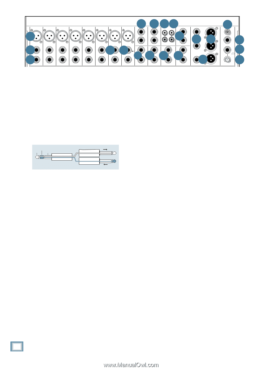
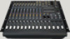
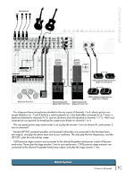
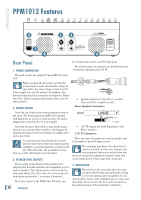
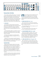
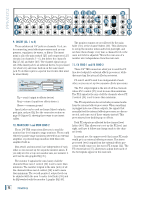
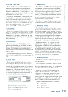
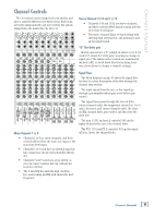
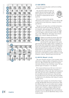
PPM1012 10 11 13 14 21 5 MIC 1 6 LINE (BAL/UNBAL) 9 INSERT MIC 2 LINE (BAL/UNBAL) INSERT MIC 3 LINE (BAL/UNBAL) INSERT MIC 4 LINE (BAL/UNBAL) INSERT MIC 5 LINE (BAL/UNBAL) INSERT MIC 6 7 LINE (BAL/UNBAL) L 1 1 15 L MIC 7 HI-Z LINE (BAL/UNBAL) 7 MIC 8 HI-Z LINE (BAL/UNBAL) 2 MON SEND 2 FX SEND R IN OUT TAPE R MAIN INSERT 8 8L (MONO) 12L (MONO) 12 L (MONO) L (MONO) INSERT INSERT INSERT R R INPUT 9/10 INPUT 11/12 R FX RTN 1 R FX RTN 2 L 16 16 L R R 17 M MAIN OUT M OO LAMP 12V 0.5A FX FOOTSWITCH TIP: FX1 RING: FX2 20 18 PHONES MAX LEVEL 19 1 2 3 4 5 6 7 8 9/10 11/12 POWER PHANTOM 9. U U U INSERT (Ch. 1 to 8) MICGAIN MIC GAIN MIC GAIN 0 -20dB +50 +30dB 0 -20dB +50 +30dB 0 -20dB +50 +30dB U MIC GAIN 0 -20dB +50 +30dB U MIC GAIN 0 -20dB +50 +30dB U MIC GAIN 0 -20dB +50 +30dB U MIC GAIN 0 -20dB +50 +30dB U MIC GAIN 0 -20dB +50 +30dB U U 2 X 800W PROFESSIONAL POWERED MIXER The monitor outputs arMeAnINoEtQUaAfLfIeZEcRted by the main EQ ASSIGN MAIN POWER AMP LIMITER -20 +20 -20 +20 MON 2 A B GAIN GAIN GAIN GAIN GAIN GAIN GAIN GAIN GAIN GAIN LOW CUT LOW CUT LOW CUT LOW CUT LOW CUT LOW CUT LOW CUT LOW CUT 15 These unbalanced 1/4" jacks on channels 1 to 6, are fader [59], or the channel faders [40]. This allows you 100Hz 100 Hz 100 Hz 100 Hz 100 Hz 100 Hz 100 Hz 100 Hz 10 COMP COMP COMP COMP COMP COMP 5 for connecting serial effects processors such as com- to set up the monitor mixes and levels just right, and 0 HI-Z HI-Z 15 10 MAIN METERS 5 0dB = 0dBu 0 OL 15 pressors, equalizers, de-essers, or filters. The insert not have them change every time a channel level or the 5 OFF MAX OFF MAX OFF MAX OFF MAX OFF MAX OFF MAX 10 U EQ U EQ U EQ U EQ U EQ U EQ U EQ U EQ U EQ U EQ 15 5 10 10 6 15 3 point is after the gain control [23] and compressor [25] main mix level is adjusted. This is the main aim of a0 HI 12kHz HI 12kHz HI 12kHz HI 12kHz HI 12kHz HI 12kHz HI 12kHz HI 12kHz HI 12kHz HI 12kHz 63 125 250 500 1K 2K 4K 8K 16K 2 4 -15 +15 -15 +15 -15 +15 -15 +15 -15 +15 -15 +15 -15 +15 -15 +15 -15 +15 -15 +15 circuiUts (on MID cU haMnID nelUs 1 -MID 6)U , butMID bUefoMrIDe thU e cMIDhanUneMlID's U moUnitor mUix: independenMcOeNf1rEoQmUALtIhZEeR main mix. MID HI HI 7 10 20 EQ [27-32] and fader [40]. The channel signal can go -15 +15 600 -15 +15 600 -15 +15 600 -15 +15 600 -15 +15 600 -15 +15 600 -15 +15 600 -15 +15 600 MID MID 2.5kHz 2.5kHz 15 -15 +15 -15 +15 U U 10 30 15 L R 10 LEVEL out of the insert jack to an external device, be processed 11. FX SEND 1 and FX SEND 2 150 1.5k 150 1.5k 150 1.5k 150 1.5k 150 1.5k 150 1.5k 150 1.5k 150 1.5k FREQ FREQ FREQ FREQ FREQ FREQ FREQ FREQ LOW MID 400Hz LOW 5 MID 400Hz 0 100 8k 100 8k 100 8k 100 8k 100 8k 100 8k 100 8k 100 8k -15 +15 -15 +15 U U U U U U U U U U 5 SET 5 RUDE SOLO 0 5 LOW LOW LOW LOW LOW LOW LOW LOW LOW LOW 10 10 (or whatever) and come back in on the same insert 80Hz 80Hz 80Hz 80Hz 80Hz 80Hz 80Hz 80Hz 80Hz 80Hz 15 15 These 1/4" TRS connectors allow you to send the FX -15 +15 -15 +15 -15 +15 -15 +15 -15 +15 -15 +15 -15 +15 -15 +15 -15 +15 -15 +15 OO OO OO OO OO OO OO OO OO OO OO OO OO OO OO OO OO OO OO OO OO OO OO OO OO OO OO OO OO OO OO OO OO OO OO OO OO OO OO OO AUX jack. To do this requires a special insert cable that must line-level outputs to external effects processors, while U SEND AUX U SEND AUX U SEND AUX U SEND AUX U SEND AUX U SEND AUX U SEND AUX U SEND AUX U SEND AUX U SEND 63 125 250 500 1K 2K 4K 8K 16K 01 PLATE REVERB 13 CHORUS POWER AMP MODE be wiredM1OtNhusly:M1ON +15 +15 MON 1 +15 MON 1 +15 MON 1 +15 MON 1 +15 MON 1 +15 disconnecting the internal effects processors. MON 1 +15 MON 1 +15 MON 1 +15 FX 1 SIG/OL FX 2 SIG/OL 02 VOCAL PLATE 03 WARM ROOM 04 BRIGHT ROOM 05 WARM LOUNGE 14 CHORUS + REVERB 15 DOUBLER 16 TAPE SLAP 17 DLY 1 BRIGHT (350ms) MON 1 MAINS MON 2 MON 1 U U U U U U U U U U U U 06 SMALL STAGE 18 DLY 1 WARM (300ms) A (L) B(R) 07 WARM THEATER 19 DLY 2 BRIGHT (250ms) STEREO MON 2 +15 U ring +15 U MON 2 +15 U MON 2 +15 U MON 2 MON 2 MON 2 S+1E5 ND to proc+e1s5 sor U U MON 2 +15 "tiUp" +15 U MON 2 OO OO FX send 1 and FX send 2 are independent of each +15 U MON 2 +15 U MON 2 +15 SEND MASTER +15 SEND MASTER 08 BRIGHT STAGE 09 WARM HALL 10 CONCERT HALL 11 CATHEDRAL 12 GATED REVERB 20 DLY 2 WARM (200ms) 21 DLY 3 BRIGHT (175ms) 22 DLY 3 WARM (150ms) 23 CHORUS + DLY (300ms) 24 REVERB + DLY (200ms) MAIN LPF tip FX 1 +15 sleeve FX (TRS plug)FX 1 1 +15 +15 FX 1 +15 FX 1 +15 FX 1 +15 FX 1 +15 TAP TO EDIT +15 FX 1 other,F1Xso +15 you +15 can FX 1 set up two separBaREtAKe effectU s proce1s20sors. U U U U U U U U U U 100 180 FX FX FX 2 2 2 +1T5his plug con+n15ects to one+o15f the miPxeArN's ChannelPInAsNert jacks. PAN FX 2 +15 PAN FX FX FX 2 2 2 +15 +15 +15 RETPUARNN from proPcAeNssor"ring" PAN FX 2 +15 The FX 1 output signal is the mix of all the channels FX 2 +15 FX 2 +15 TAP DELAY TAP DELAY MUTES CH 1-12 FX 1 +20 TAPE IN FX 1 75Hz 200Hz TO MON 1 TO MON 2 MONO OUT PAN PAN whose FX 1 control PAN INT FX MUTE [35] isINTFX MUTE set to U more U than minimum. OO OO LR LR LR LR LR LR LR L R ThLeR FX 2 LsRignal is the mix of all the+15channe+1l5s whoseMAX FX OO OO Tip = send (output to effects device) 2 control [36] is set to more than minimum. Ring = return (input from effects device) 1 2 3 4 5 6 Sleeve = common ground dB dB dB dB dB 10 10 10 10 10 dB 10 dB 10 5 OL 5 OL 5 OL 5 OL 5 OL 5 OL 5 7 dB 10 OL 5 InUsert+10 jacU ks can be +10 U used +10 U as channel +10 +10 U dUirec+1t0 ouU tpu+1t0 s; U 0 0 0 0 0 0 0 5 5 5 5 5 5 5 5 post-gain, and pre-EQ. See the connector section on -20 -20 -20 -20 -20 -20 -20 10 10 10 10 10 10 10 10 page20 30 (fig20ure G)20 showin20 g three20 ways to20 use in20 sert 20 30 30 30 30 30 30 30 30 SOLO SOLO SOLO SOLO SOLO SOLO SOLO cabl4500es. 40 50 40 50 40 50 40 50 40 50 40 50 40 50 60 60 60 60 60 60 60 60 8 Th9e/10FX o1u1/t12puts here FX RTN1 doFXnRoTNt2 incluMdONe1procMeOsNs2ed auMdAiINo from dB 10 thedB 10 internad1B0l effectsd1B0 processd1B0ors. When dB 10 somedt1B0hing OL 5 OL 5 OL 5 5 5 5 5 +10 isU plu+10ggeU d into +10 oUne of theU se outpUuts, theUsignals tUhat 0 0 0 -20 n5orm-2a0 lly5 feed-20 th5e intern5al effect5s proces5sor are d5 iscon- 10 10 10 10 10 10 10 n20ected, a20 nd com20e out of20these ou20 tputs in20stead. T20his prevents you from doubling-up on effects. 30 SOLO 40 30 SOLO 40 30 SOLO 40 30 SOLO 40 30 SOLO 40 30 SOLO 40 50 50 50 50 50 50 60 60 60 60 60 60 30 SOLO 40 50 60 OO OO OO OO OO OO OO OO OO OO OO OO OO OO OO 10. MON SEND 1 and MON SEND 2 Both FX outputs are affected by the channel level faders [40]. This allows you to set up the FX level just These 1/4" TRS connectors allow you to send the right, and have it follow any change made to the chan- monitor line-level output to stage monitors. These could nel levels. either be passive stage monitors powered by an external amplifier, or powered stage monitors with their own amplifier built in. In normal use, the unprocessed (dry) mono FX sends would go to an external effects processor. The stereo processed (wet) output from the external effects pro- Mon send 1 and mon send 2 are independent of each other, so you can set up two separate monitor mixes. If you only need to set up one monitor mix, use monitor 1, cessor would connect to the stereo FX returns [12]. The FX return faders [57] allow you to adjust how much of the wet signals appear in the main mix. as it has its own graphic EQ [45]. The monitor 1 signal is the sum (mix) of all the channels whose mon 1 control [33] is set to more than minimum. The monitor 2 signal is the sum (mix) of all the channels whose mon 2 control [34] is set to more than minimum. The overall monitor 1 output level can be adjusted with the mon 1 master level fader [58] and its EQ tweaked with the monitor 1 graphic EQ [45]. 12 PPM1012
-
 1
1 -
2
-
3
-
4
-
5
-
6
-
 7
7 -
 8
8 -
 9
9 -
 10
10 -
 11
11 -
 12
12 -
 13
13 -
 14
14 -
 15
15 -
 16
16 -
 17
17 -
18
-
19
-
20
-
21
-
22
-
23
-
24
-
25
-
26
-
27
-
28
-
29
-
30
-
31
-
32
-
33
-
34
-
35
-
36
 |
 |